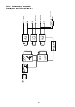
251
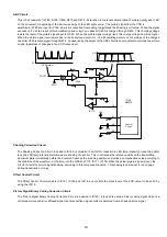
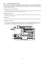
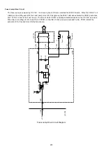
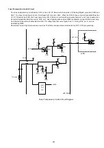
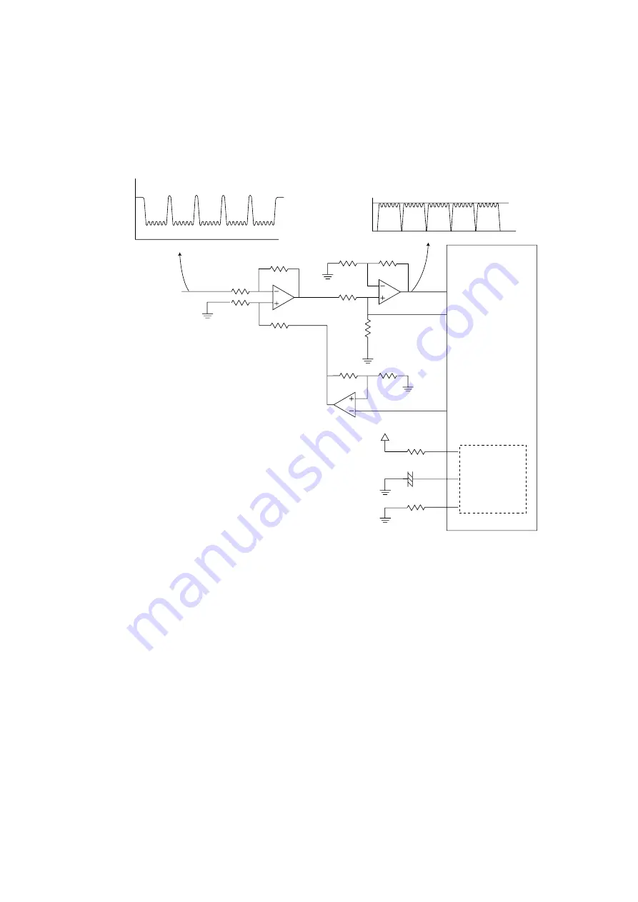
ABC Circuit
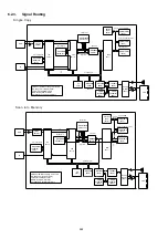
This circuit consists of IC180, IC160, C650, R673 and R674. Its function is to prevent deterioration of picture quality due to dirt
on the document or degrading of the luminous energy of the LED light source. The picture signal from the CCD is
amplified in IC180 and input to IC160, where it is converted from analog to digital and the shading is corrected. When the signal
e3.0V as the result of this amplification and correction, capacitor C650 is charged through R673. This charging voltage
lowers the level of the picture signal input to IC180. When the picture signal voltage rises, this charge voltage becomes higher.
When the picture signal level lowers due to the background color, etc., of a transmitting document, the voltage of the charged
capacitor C650 is discharged through R674. Consequently, the output of the ABC circuit is kept constant to maintain the picture
quality, regardless of changes in the CCD output level.
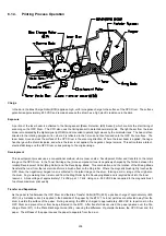
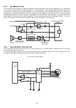
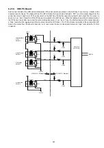
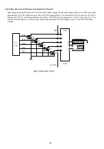
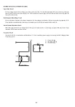
Shading Correction Circuit
The Shading Correction Circuit, included in IC160, is provided to correct for reduction in LED lamp intensity around the optical
lens and LED lamp intensity distortion due to shading of each bit. This circuit scans the reference white on the transmitting
document plate immediately before the document reaches the scanning position and writes a compensation value according to
the distortion of the waveform, at the time, into the S-RAM (IC170, IC171, IC172).When the actual picture signal is input, the
circuit corrects the picture signal shading, according to this compensation value. This shading is carried out for each page
during transmission or copy.
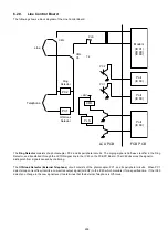
Offset Control Circuit
The Offset Control Circuit consists of IC161, IC160 and IC118, and controls the black level of the CCD output to be at 0V by
using the IC118.
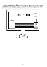
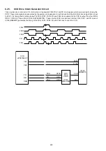
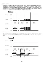
Picture Signal Binary Coding Correction Circuit
The Picture Signal Binary Coding Correction Circuit is included in IC160. It is used to obtain a binary coding signal which is a
corrected picture and error diffused signal of a false halftone signal, which is detected from a shaded picture signal.
CCD Output
ABC Circuit Output
+5V
R673
C650
R674
IC180
IC180
32
36
19
IC112
IC160
M86075
Control
Circuit
41
39
40
AGN
VOUT1
0V
3.0V
0V
Summary of Contents for Panafax DX-2000
Page 2: ......
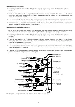
Page 27: ...27 9 1 Screw 19 10 Release two Latch Hooks 11 Remove the SNS Assembly 121 9 10 11 ...
Page 49: ...49 2 15 Screw Identification Template ...
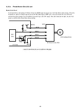
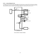
Page 57: ...57 3 7 3 Option Cassette Circuit 555 748 728 744 928 953 730 731 731 952 944 930 931 931 ...
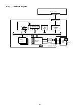
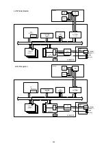
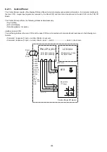
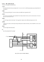
Page 58: ...58 3 7 4 LAN Control Circuit 522 CN50 1102 1104 1101 N C N C RD N C N C RD TD TD ...
Page 59: ...59 3 7 5 Page Description Language Printer Interface Kit ...


