254
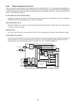
6.2.7.
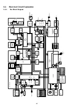
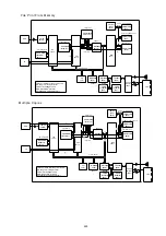
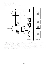
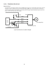
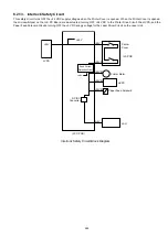
Line Monitor Circuit
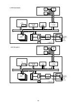
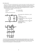
The Line Monitor Circuit consists of an operational amplifier (IC100), analog master (IC91) and its peripheral circuits. Its function is
to monitor the dial tone, DTMF tone, response signals, etc. over the speaker. It also sounds the output of the key touch tones,
alarm tones, etc. from the panel CPU over the speaker. The received signal from the Ain (M) passes through an AGC circuit and is
conditioned by the Analog Front-End DSP (IC90) and is then input to the Analog SW2 for volume control. The signal is then input
to the Speaker Amplifier (IC100, Q91, 92), where it is amplified to a level sufficient to drive the speaker. The key touch tones and
Buzzer Signals from the panel are input to the Analog SW2 for volume control and then input to the Speaker Amplifier. The monitor
tone from the phone line and the buzzer tone from the panel can be adjusted from the Control Panel.
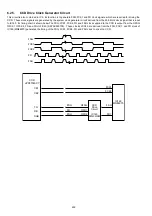
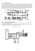
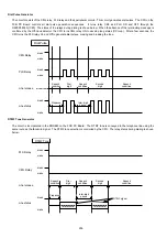
6.2.8.
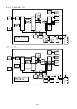
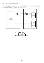
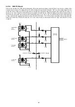
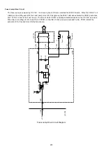
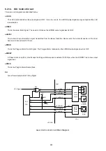
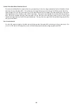
Transmit Motor Control Circuit
The transmit motor is a stepper motor powered by +24 VDC and driven by a 1/2-phase excitation, greater step division is provided
by controlling the phase circuit in steps.
The stepping signal and chopping current control signals (pTINA, pTTDA, pTINB and pTTDB) are sent to the chopper drive circuit,
comprised of IC190 and its peripheral circuitry, from the IC150 (S-CPU) output port.
HYSIG
RX signal
Speaker
Speaker Amplifier
IC100, Q91, 92
Buzzer Signal
from Panel
Analog SW2
Analog SW1
Analog Master
Analog Front-End DSP
(IC90)
IC91
Ain(M)
AGC
Aout(M)
Aout(V)
TX signal
LPF Fc: 7.8 KHz
LPF Fc: 7.8 KHz
HYBSR
S-CPU
IC150
+5V
+5V
Q193
Q194
+24V
MGND
Transmit Motor
Motor
Driver
IC190
Motor Control Signal
MGND
F190
Tx Motor Driver Circuit Block Diagram
(pTINA, pTTDA, pTINB and pTTDB)
Summary of Contents for Panafax DX-2000
Page 2: ......
Page 27: ...27 9 1 Screw 19 10 Release two Latch Hooks 11 Remove the SNS Assembly 121 9 10 11 ...
Page 49: ...49 2 15 Screw Identification Template ...
Page 57: ...57 3 7 3 Option Cassette Circuit 555 748 728 744 928 953 730 731 731 952 944 930 931 931 ...
Page 58: ...58 3 7 4 LAN Control Circuit 522 CN50 1102 1104 1101 N C N C RD N C N C RD TD TD ...
Page 59: ...59 3 7 5 Page Description Language Printer Interface Kit ...