
261
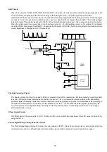
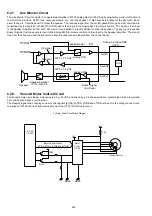
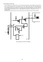
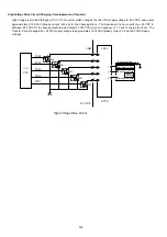
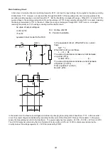
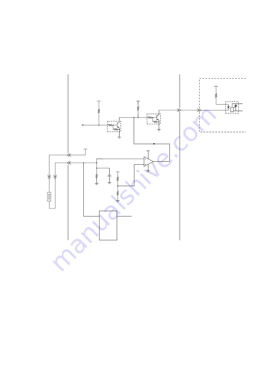
Fuser Temperature Control Circuit
The fuser temperature is controlled by IC51 on the LPC PC Board, which contains A/D (Analog/Digital) converters ANI0 and
ANI7. The Fuser Temperature Control Circuit uses A/D converter, ANI1. When the PC301 drive current is transmitted from the
LPC PC Board to the LVPS, the Fuser Lamp turns ON. IC55 is a converter with open output at pins 1 and 7 and is used as an
abnormal temperature detection circuit. IC55, pin 1, has a high impedance when Q602 is activated, turning ON the Fuser Lamp.
An abnormal temperature is detected when the VTH voltage level becomes higher than V+, forcing IC55, pin 1 Low and
deactivating Q602.
Abnormally low and high temperatures, as well as Thermistor release status, are detected by IC51 (CPU) programming.
GND
Q602
3
GND
Q601
3
+5v
R616
2
2
+5v
R615
R613
2
IC55
4
1
3
GND
GND
C602
R614
GND
R612
+5v
+24V
GND
TP201
PC301
1
2
6
4
+24v
R201
+5v
Thermistor
LVPS
nSSRA
nSSRA
8
1
1
47
LPC PCB
1
2
CN56
9
CN67
9
CN32
Fuser Temperature Control Circuit Diagram
(ANI1)
IC51
CPU
Summary of Contents for Panafax DX-2000
Page 2: ......
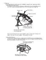
Page 27: ...27 9 1 Screw 19 10 Release two Latch Hooks 11 Remove the SNS Assembly 121 9 10 11 ...
Page 49: ...49 2 15 Screw Identification Template ...
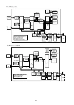
Page 57: ...57 3 7 3 Option Cassette Circuit 555 748 728 744 928 953 730 731 731 952 944 930 931 931 ...
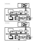
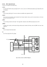
Page 58: ...58 3 7 4 LAN Control Circuit 522 CN50 1102 1104 1101 N C N C RD N C N C RD TD TD ...
Page 59: ...59 3 7 5 Page Description Language Printer Interface Kit ...