
321
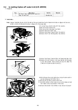
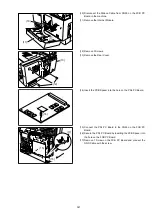
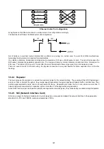
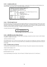
(10) Disconnect the Ribbon Cable from CN50 on the FCB PC
Board in the machine.
(11) Remove the Internet Module.
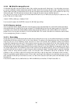
(12) Remove 3 Screws.
(13) Remove the Rear Cover.
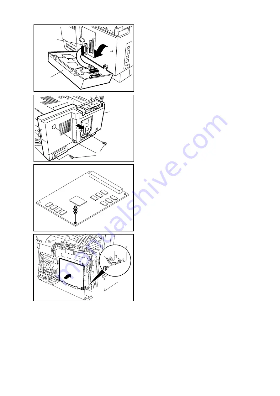
(14) Insert the PCB Spacer into the hole on the PDL PC Board.
(15) Connect the PDL PC Board to the CN55 on the FCB PC
Board.
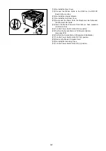
(16) Secure the PDL PC Board by inserting the PCB Spacer into
the hole on the FCB PC Board.
(17) Remove 1 Screw on the FCB PC Board and connect the
GND Cable with the screw.
(11)
(10)
(13)
(12)
(14)
(15)
(17)
(16)
Summary of Contents for Panafax DX-2000
Page 2: ......
Page 27: ...27 9 1 Screw 19 10 Release two Latch Hooks 11 Remove the SNS Assembly 121 9 10 11 ...
Page 49: ...49 2 15 Screw Identification Template ...
Page 57: ...57 3 7 3 Option Cassette Circuit 555 748 728 744 928 953 730 731 731 952 944 930 931 931 ...
Page 58: ...58 3 7 4 LAN Control Circuit 522 CN50 1102 1104 1101 N C N C RD N C N C RD TD TD ...
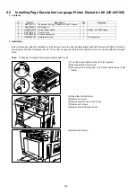
Page 59: ...59 3 7 5 Page Description Language Printer Interface Kit ...