


Table of Contents
3
General Description ................................... 5
Overview...................................................5
General Features and Functions ..............5
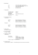
General Specifications..............................8
Scanner Specifications ...........................11
Printer Specifications ..............................11
Power......................................................12
Environment............................................12
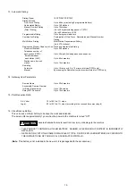
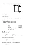
Construction............................................13
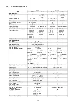
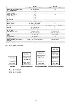
Specification Table .................................15
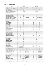
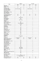
1.10. Function Table ........................................17
Disassembly Instructions ......................... 20
General Disassembly Flowchart .............20
Paper Guide Cover (110),
Transmit Guide (117),
SNS Assembly (121) ..............................26
Toner Sensor (639),
Timing Sensor (610),
Bias Transfer Roller (630) ......................37
Pressure Roller (409),
Eject Roller (422) ....................................41
2.11. Fan Duct (520), Printer Motor (650),
Motor Bracket (641) ............................... 43
2.12. Laser Unit (429), Feed Roller (618),
No Paper Actuator (609),
Catch Magnet (730) ............................... 47
2.14. High Voltage Power Supply (HVPS)
(506) ....................................................... 48
2.15. Screw Identification Template ................ 49
Maintenance, Adjustments and
Check Points ........................................... 50
Required Tools ...................................... 50
Periodic Maintenance Points.................. 50
Periodic Maintenance Check List ........... 51
Updating the Firmware ........................... 52
ADF Pressure......................................... 53
Printer Unit Test ..................................... 54
General Circuit Diagram......................... 55
FCB PCB................................................ 60
LPC PCB ................................................ 92
3.10. LCU / LCE PCB.................................... 101
3.11. SRU PCB (Optional) ............................ 103
3.12. Low Voltage Power Supply PCB
(POW) .................................................. 104
3.13. High Voltage Power Supply PCB
(HVPS) ................................................. 105
3.14. CST2 PCB (Option).............................. 106
3.15. CST3 PCB (Option).............................. 110
3.16. LANB PCB ........................................... 113
3.17. LANC PCB ........................................... 120
3.18. Page Description Language
Printer Interface PCB ........................... 122
Troubleshooting..................................... 132
Initial Troubleshooting Flowchart ......... 132
Improper LCD Display .......................... 133
Information Codes (INFO. CODES) ..... 134
Printed Copy Quality Problems ............ 147
Document Feeder (ADF) ...................... 163
Communications .................................. 166
Troubleshooting the LAN Interface ...... 171
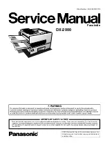
Summary of Contents for Panafax DX-2000
Page 2: ......
Page 27: ...27 9 1 Screw 19 10 Release two Latch Hooks 11 Remove the SNS Assembly 121 9 10 11 ...
Page 49: ...49 2 15 Screw Identification Template ...
Page 57: ...57 3 7 3 Option Cassette Circuit 555 748 728 744 928 953 730 731 731 952 944 930 931 931 ...
Page 58: ...58 3 7 4 LAN Control Circuit 522 CN50 1102 1104 1101 N C N C RD N C N C RD TD TD ...
Page 59: ...59 3 7 5 Page Description Language Printer Interface Kit ...