32
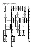
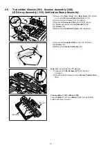
2.6.
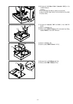
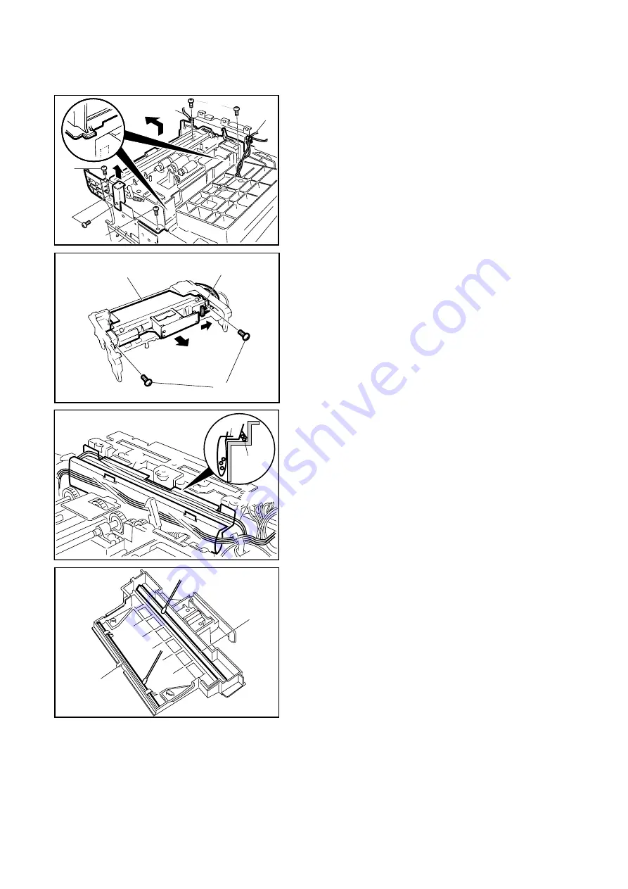
Transmitter Chassis (301), Scanner Assembly (340),
LED Array Assembly (333), Verification Stamp Assembly
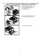
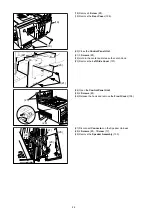
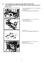
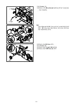
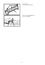
(1) Remove the Front Cover (105), Rear Cover (108) (Refer
to 2.3.) and the Control Panel Unit (Refer to 2.5.).
(2) Remove all the harnesses from the clamps.
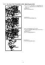
(3) Disconnect Connector CN8 on the FCB PC Board.
(4) 1 Screw and remove the Front Bracket 2 (136).
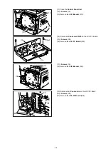
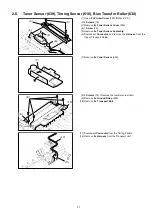
(5) 4 Screws (19).
(6) Remove the Transmitter Chassis (301) Assembly.
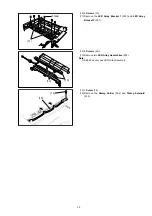
(7) Disconnect Connector CN30 on the CCD PC Board.
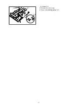
(8) 2 Screws (19).
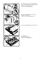
(9) Remove the Scanner Assembly (340).
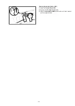
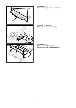
Note: When reinstalling the CCD Harness,
1. Separate the CCD Harness (545) from the other
harnesses.
2. Place the other harnesses into the Harness Protector Film
(556).
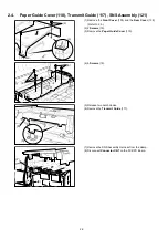
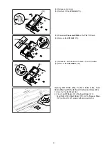
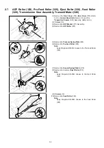
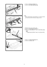
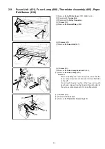
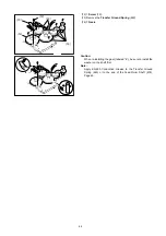
Cleaning Mirror 1 (337), Mirror 2 (338)
Clean the Mirror 1 (337) and Mirror 2 (338) with a soft cloth,
soaked with isoproyl alcohol.
(2)
(2)
(4)
(5)
(5)
(5)
(6)
(7)
(8)
(9)
(1)
(2)
(1)
(2)
Mirror 1
Mirror 2
Summary of Contents for Panafax DX-2000
Page 2: ......
Page 27: ...27 9 1 Screw 19 10 Release two Latch Hooks 11 Remove the SNS Assembly 121 9 10 11 ...
Page 49: ...49 2 15 Screw Identification Template ...
Page 57: ...57 3 7 3 Option Cassette Circuit 555 748 728 744 928 953 730 731 731 952 944 930 931 931 ...
Page 58: ...58 3 7 4 LAN Control Circuit 522 CN50 1102 1104 1101 N C N C RD N C N C RD TD TD ...
Page 59: ...59 3 7 5 Page Description Language Printer Interface Kit ...