background image

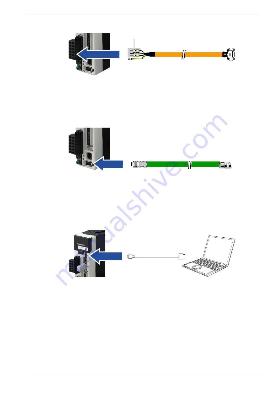
 3.2 Connectors of the servo driver

U, V, W

U

V

W

MFMCA0xxxWJD ACS **/YY

Wiring of the XB connector for the motor power supply

X6 connector (encoder connector)

Connect the encoder cable to the X6 connector.

MFECA0xxxWJD   ACS   **/YY

Wiring of the X6 connector for the encoder connection

X1 connector (USB connector for PC connection)

The servo driver is configured using the PC configuration software PANATERM. Use a
commercially available USB A to mini-B cable to connect the PC to the servo driver.

Connector X1 for PC connection

QS5001_V1.0_EN

 9

Summary of Contents for PANATERM

Page 1: ...Servo Drives Quick Start Guide PANATERM Real time auto gain tuning QS5001_V1 0_EN 2019 07 www panasonic electric works com ...

Page 2: ...ntinuous improvement of the design and performance of its products Therefore we reserve the right to change the manual product without notice In no event will PEWEU be liable for direct special incidental or consequential damage resulting from any defect in the product or its documentation even if advised of the possibility of such damages Please direct support matters and technical questions to y...

Page 3: ... 2 About this document 4 1 3 Related documents 4 1 4 Available software 5 2 Functional overview 6 3 Wiring 8 3 1 Recommendations for wiring 8 3 2 Connectors of the servo driver 8 4 Perform real time auto gain tuning 10 5 Help us improve 12 6 Record of changes 13 QS5001_V1 0_EN 3 ...

Page 4: ...lick on the following links to download the documents from our Panasonic Download Center Information on wiring position control and parameters Operating Instructions Overall AC Servo Motors Driver MINAS A5 series Operating Instructions Overall AC Servo Motors Driver MINAS A6 series Information on using the PANATERM configuration software Operation Manual Set up support software PANATERM Ver 6 0 In...

Page 5: ... QS5000 PANATERM Trial run QS5002 PANATERM Fit gain tuning 1 4 Available software The following software is available free of charge in our Panasonic Download Center Click on the link to start the download PC configuration software PANATERM QS5001_V1 0_EN 5 ...

Page 6: ...ou should perform real time auto gain tuning on the machine with the servo motor and the mechanical loads connected and with the actual movements Usually auto tuning has the following goals 1 Reduce the settling time to reduce cycle times 2 Reduce mechanical vibration to increase the life time of the machine 3 Reduce overshoot and undershoot to reach the target position within the allowed hysteres...

Page 7: ...1 4 Available software Continuous movement between two mechanical limits QS5001_V1 0_EN 7 ...

Page 8: ...e For detailed information on reducing EMI please refer to Recommendations for EMC compliant wiring of servo drivers and motors 3 2 Connectors of the servo driver XA connector main power connector Connect the power supply cable to the XA connector For a 1 phase power supply of 230V connect a 2 wire cable to the servo driver as illustrated The L2 pin is not used in 1 phase mode L N Wiring of the XA...

Page 9: ...encoder cable to the X6 connector MFECA0xxxWJD ACS YY Wiring of the X6 connector for the encoder connection X1 connector USB connector for PC connection The servo driver is configured using the PC configuration software PANATERM Use a commercially available USB A to mini B cable to connect the PC to the servo driver Connector X1 for PC connection QS5001_V1 0_EN 9 ...

Page 10: ...driver connected 3 Select OK and confirm the connected series by selecting your type of servo driver 4 Start a trial run following the instructions in Quick Start Guide QS5000 PANATERM Trial run 5 While the motor is performing a repetitive constant movement select the Tuning tab 1 1 Tuning tab 6 Select the Damping control tab 1 1 Damping control tab 7 Select 2 2 filters are valid in the Filter Mod...

Page 11: ...ue and if necessary decrease the rigidity to an appropriate value 10 Select Invalid in the Select Mode list box 11 Select the EEP icon to save the parameters in the EEPROM of the servo driver A dialog shows the gain parameters related to the inertia moment which have been changed 12 Confirm these values 13 Shut down and restart the system The system is now ready to perform the required positioning...

Page 12: ...ve any questions or if you have any suggestions for improvement In that case we ask you to include the Quick Start Guide number in the email subject line You can find the number starting with QS on the cover page Servo peweu eu panasonic com 49 0 8945354 2750 12 QS5001_V1 0_EN ...

Page 13: ...3 2 Connectors of the servo driver 6 Record of changes QS5001_V1 0_EN 2019 07 First edition QS5001_V1 0_EN 13 ...

Page 14: ...a del Commercio 3 5 Z I Ferlina 37012 Bussolengo VR Tel 39 0456752711 Fax 39 0456700444 www panasonic electric works it Nordic Countries Panasonic Electric Works Europe AG Panasonic Fire Security Europe AB Filial Nordic Knarrarnäsgatan 15 164 40 Kista Sweden Tel 46 859476680 Fax 46 859476690 www panasonic electric works se Jungmansgatan 12 21119 Malmö Tel 46 40 697 7000 Fax 46 40 697 7099 www pana...

Reviews: