74
AHU Kit – Installation Instructions –
11/2021
Electrical Wiring
5
5.4 Wiring layout
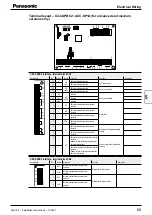
Wiring layout – MAH2 models
PAW-160MAH2L for
and
Legend
Light
PA
W
-160MAH2L
TH1
Air intake temperature sensor
TA
X
TH2
Indoor coil thermistor E1
X
TH4
Indoor coil thermistor E3
X
TH5
Air outlet temperature sensor BL
X
CZ-R
TC2 / CZ-R
TC4*
Remote controller
X
CR-SV80A
RAP
valve control PCB
X
CR-UXRP71B-P
Main PCB
X
Light
PA
W
-160MAH2L
1Z / 2Z
Auxiliary power relay
X
TR1
Power transformer
X
PA
W
-T10
External signal control PCB
X
ACC-SP1A
External signal control PCB
–
TR-16 /
TR-16e*
Thermostat
–
PT100
Supply air temperature sensor
–
* Depending on
AHU Kit generation
1
3
AC IN (BLK
)
1
2
OC
(BL
U)
1
3
RC
(BL
U)
1
2
EXC
T
(RED
)
1
2
3W
AY
(BLK
)
3
4
5
1
3
OP1
(Y
EL)
1
3
FA
N
(WHT
)
5
7
9
1
3
T20 (G
RY
)
1
3
TR
ANS
-P
(WHT
)
1
2
TR
ANS
-S
(WHT
)
3
4
1
2
PM
V
(WHT
)
3
4
5
6
1
2
HBS (Y
EL)
CR-UXRP71B
-P
1
2
TA
(Y
EL)
1
2
E1
(RED
)
1
3
E3
(BRN)
1
2
BL
(GRN)
1
3
FS
(RED
)
1
2
PNL
(BRN)
1
2
FAN DRIVE
(WHT
)
L
N
U1
U2
R1
R2
EX1
EX2
1
2
3
4
5
1
3
3W
AY (
WHT
)
POWER (
WHT
)
CR-SV80A
1
3
SV1/CN003 (RED
)
5
7
9
6
1
2
3
4
5
6
CONNEC
TOR 6P
(Y
EL)
1Z
7
5
8
3
1
2Z
7
5
8
3
1
TERMINAL
1Z5
1Z3
TERMINAL
OP3
2Z7
05
06
M1.1
M1.2
M1.3
M1.4
M1.5
TERMINAL
TA
1
TA
2
E1.1
E1.2
E3.1
E3.2
BL1
BL2
FS1
FS2
TERMINAL
FD1
FD2
1
2
FIL
TER
(WHT
)
FI1
FI2
1
3
HU1
(RED
)
HU1
HU2
4POL
PK1-B
10
PK1-
A
PA
W
-T10
T10
9
8
1
2
3
4
5
6
1
2
3
4
7
6
5
(WHT
)
1
2
3
4
5
6
T10 (Y
EL)
+
E
1
2
OPTION
(WHT
)
3
4
5
6
ON1
ON2
ON3
ON4
ON5
ON6
PE
CZ
-R
TC2/4
R1
R2
M1.6
BRN
BRN
WHT
WHT
RED
RED
TR1
ORG
RED
YEL
BLK
GRY
ORG
RED
YEL
BLK
GRY
BLK
BLK
BLK
BLK
BLK
BLK
BLK
BLK
RED
GRN
WHT
RED
BLK
BLU
PNK
BLU
WHT
BLK
RED
WHT
YEL
BLU
BLK
WHT
RED
BLK
WHT
RED
YEL
BLU
RED
WHT
BLK
VLT
GRY
YEL
ORG
VLT
WHT
BRN
RED
WHT
VLT
BRN
YEL
RED
WHT
BLK
BLU
ORG
OR
G
RED
YE
L
BLK
G
RY
WHT
WHT
BLK
WHT
BLK
ORG
ORG
VLT
GRY
WHT
RED
WHT
WHT
BLK
PNK
BLU
BRN
YEL
BLU
RED
WHT
WHT
WHT
RED
RED
t°
TH1
t°
TH2
t°
TH4
t°
TH5
06.08.2021, cH
Headlines adjusted/corrected (the previous ones re-
ferred to the ECOi/ECO G and PACi systems, which
was not right, because it is the AHU Kit wiring
which is shown here).
06.08.2021, JW
ok, but please place the ECOi and ECO G blue label
also here, for easier identification. Best to place
them on each MAH2 page
Summary of Contents for PAW-280PAH3M-1
Page 2: ...Notes ...
Page 113: ...Notes ...


