70
Control
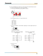
7. Restore and fasten the upper mounting board in its original position, and close the AHU Kit
enclosure again (see “4.1 Installation of AHU Kit“ – step 5).
Case 3: 0–10 V demand control by an external BMS
To set the thermostat for 0–10 V demand control by an external building management system
(BMS), perfom the following steps:
1. Open the AHU Kit enclosure (see “4.1 Installation of AHU Kit“ – step 2), and remove the up-
per mounting board.
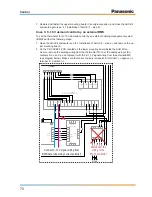
2. On the CZ-CAPBC2 PCB, located on the lower mounting board inside the AHU Kit en-
closure, remove the existing wiring from the thermostat TR-16 at the analogue input (AI)
contacts No. 3 and 4, and replace it with the 0–10 V signal wiring from the external BMS
(see diagram below). Make sure that correct polarity is observed: terminal 3 = negative (–),
terminal 4 = positive (+).
1
3
AC IN
(BLK)
1 2
OC
(BLU)
1 3
RC
(BLU)
1 2
EXCT
(RED)
1 2
3WAY
(BLK)
3 4 5
1 3
OP1
(YEL)
1 3
FAN
(WHT)
5 7 9
1 3
T20
(GRY)
1 3
TRANS-P
(WHT)
1 2
TRANS-S
(WHT)
3 4
BRN
BRN
WHT
WHT
RED
RED
TR1
1 2
PMV
(WHT)
3 4 5 6
1 2
HBS
(YEL)
CR-UXRP71B-P
1 2
TA
(YEL)
BLK
BLK
1 2
E1
(RED)
BLK
BLK
1 3
E3
(BRN)
BLK
BLK
1 2
BL
(GRN)
BLK
BLK
1 3
FS
(RED)
RED
1 2
PNL
(BRN)
GRN
1 2
FAN DRIVE
(WHT)
WHT
RED
BLK
BL
U
PNK
BL
U
WHT
BLK
RED
WHT
L
N
U1 U2
R1
R2
EX1 EX2
YEL
BL
U
BLK
WHT
RED
1 2 3 4 5
1 3
3WAY (WHT)
POWER (WHT)
CR-SV80B
1 3
SV1 (RED)
5 7 9
BLK
WHT
RED
YEL
BL
U
6
1
2
3
4
5
6
CONNECTOR 6P
(YEL)
1 3
SV2 (RED)
5 7 9
BLK
WHT
RED
YEL
BL
U
1
2
3
4
5
6
CONNECTOR 6P
(YEL)
RED
WHT
BLK
1Z
7
5
8
3
1
2Z
7
5
8
3
1
1
3
OP3
(YEL)
TERMINAL
VL
T
G
RY
1Z5 1Z3
TERMINAL
OP3 2Z7
05
06
YEL
O
RG
VL
T
WHT
BRN
M1.1 M1.2 M1.3 M1.4 M1.5
TERMINAL
TA1 TA2
E1.1 E1.2
E3.1 E3.2
BL1 BL2
FS1 FS2
TERMINAL
FD1 FD2
1 2
FILTER
(WHT)
RED
WHT
FI1 FI2
1 3
HU1
(RED)
VL
T
BRN
HU1 HU2
CZ-CAPBC2
COM DO2 COM DO1
1
2
3
4
5
6
7
8
9
10 11 12 13 14 15
CN2
CN1
4POL
PK1-B
10
PK1-A
PAW-T10
T10
9
8
1
2
3
4
5
6
1
2
3
4
7 6 5
(WHT)
1
2
3
4
5
6
T10
(YEL)
+
E
1 2
OPTION
(WHT)
3 4 5 6
YEL
RED
WHT
BLK
BL
U
O
RG
ON1 ON2 ON3 ON4 ON5 ON6
TR-16
PT100
PE
COM DI1 DI2 DI3 COM DO2 COM DO1
TERMINAL
1
2
3
4
5
6
7
8
9
10
PT10 PT9 PT8
TERMINAL
BLK
BL
U
BLK
BL
U
BRN
YEL
RED
WHT
RED
RED
WHT
+
-
RED
BLK
BLK
ORG
RED
YEL
BLK
GRY
WHT
BL
U
YEL
O
RG
BRN
BRN
ORG
YEL
BLU
WHT
BLK
CZ-RTC2
R1
R2
WHT
BLK
O
RG
O
RG
G
RY
RED
WHT
RED
WHT
WHT
BLK
PNK
BL
U
BLK
YEL
BL
U
RED
t°
TH1
t°
TH2
t°
TH4
t°
TH5
O
RG
RED
YEL
BLK
G
RY
O
RG
RED
YEL
BLK
G
RY
WHT
G
RY
WHT
M1.6 M2.1 M2.2 M2.3 M2.4 M2.5
O
RG
RED
YEL
BLK
WHT
WHT
BLK
VLT
WHT
RED
RED
Connect 0–10 V signal wiring from
BMS here (observing correct polarity!)
Disconnect the
wiring of the
TR-16 controller
–
+


