background image

83

4.5.11.b. Display of Detailed Information of Neighbor Table

On  the  Neighbor  Table,  pressing  "D"  opens  the  Neighbor  Detail  Information          
screen, as shown in Fig. 4-33. On this screen, you can display detailed information             
of the Neighbor Table.

 PN28248 Local Management System
 Neighbor Table -> Neighbor Detail Information

 Index             : 1
 Local Port        : 1
 Discovered Time   : 000day(s), 00hr(s), 00min(s), 00sec(s)
 Last Update Time  : 000day(s), 00hr(s), 00min(s), 00sec(s)
 ChassisId         : xx:xx:xx:xx:xx:xx (MAC Address)
 PortId            : xx:xx:xx:xx:xx:xx (MAC Address)
 System Name       : 
 System Capability : x / x (Supported / Enabled)
                     (O:Other  R:Repeater  B:Bridge W:WLAN Access Point
                      r:Router T:Telephone D:DOCSIS cable device S:Station Only)
 Port Description  : 
 System Description: 

 -------------------------------- <COMMAND> -----------------------------------
 [N]ext Entry                          [Q]uit to previous menu
 [P]revious Entry

 Command>
 Enter the character in square brackets to select option

Fig. 4-33 Display of Detailed Information of Neighbor Table

Screen Description

Index

Displays the entry number.

Local Port

Displays the port number that received LLDP frames.

Discovered Time

Displays the time when the first LLDP frame was received.

Last Update Time

Displays the time when the last LLDP frame was received.

ChassisId

Displays the Chassis ID of the entry.

PortId

Displays the port ID of the entry.

System Name

Displays the system name of the entry.

System Capability

Displays the capability information of the entry.

Port Description

Displays the interface information of the entry.

System Description

Displays the overview information of the entry.

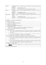
Available commands are listed below.

N

Display the next page.

Press "N" to display the next entry.

P

Display the previous page.

Press "P" to display the previous entry.

Q

Return to the parent menu.

Summary of Contents for PN28248

Page 1: ...k you for purchasing our product This manual provides important information about safe and proper operations of this Switching Hub Please read the Important Safety Instructions on pages 3 to 6 If you disassemble this Switching Hub for any reason damage is not covered by warranty ...

Page 2: ...The target model for this Operation Manual is as follows Model name Model number Firmware version Switch M24eGLPWR PN28248 ID 1 0 0 04 and higher PN28248 TH PN28248 MY PN28248 SG 2 ...

Page 3: ...ould lead to fire electric shock and or equipment failure Do not handle the power cord with wet hand Deviation could lead to electric shock and or equipment failure Do not handle this Switching Hub and connection cables during a thun derstorm Deviation could lead to electric shock Do not disassemble and or modify this Switching Hub Deviation could lead to fire electric shock and or equipment failu...

Page 4: ...t sunlight and or high tem perature Deviation could lead to high internal temperature and fire Do not install any module other than the separately sold SFP module PN54021K PN54023K to SFP extension slot Deviation could lead to fire electric shock and or equipment failure Do not install this Switching Hub at the location with continuous vibra tion or strong shock or at the unstable location Deviati...

Page 5: ...failure Connect the power cord firmly to the power port Deviation could lead to electric fire shock and or malfunction Unplug the power cord if the Status ECO LED Status ECO mode FAN LED fan sensor or TEMP LED temperature sensor blinks in orange system fault Deviation such as keeping connected for a long time could lead to fire Handle the Switching Hub carefully so that fingers or hands may not be...

Page 6: ... arrester SPD Surge Protective Device at the twisted pair port side of the Switching Hub Overcurrent and or overvoltage caused by lightning may affect this Switching Hub through a power source connected to the power port and or a grounding line causing equipment failure When there is a possibility of overcurrent over voltage from lightning affecting this Switching Hub from a power source and or a ...

Page 7: ...e SFP extension slot Do not place charged objects in the proximity of them Static electricity could lead to equipment failure Do not put the modular plug of the connected twisted pair cable on objects that can carry static charge such as carpet Do not place it in the proximity Static electricity could lead to equipment failure Do not put a strong shock including dropping to this Switching Hub Devi...

Page 8: ...may result in fire electric shock breakdown and or malfunction In addition do not cover the bent hole of this Switching Hub Deviation could lead to high internal temperature equip ment failure and or malfunction If used at a temperature out of the operating temperature range the protection equipment becomes activated and PoE power supply stops Do not stack Switching Hubs When placing Switching Hub...

Page 9: ...ing to Power 25 4 Configuration 26 4 1 Login 27 4 2 Basic Operations on the Screen 29 4 3 Main Menu 31 4 4 General Information Menu 32 4 5 Basic Switch Configuration 34 4 5 1 System Administration Configuration 36 4 5 2 System IP Address Configuration 38 4 5 3 SNMP Configuration 40 4 5 3 a SNMP Management Configuration 41 4 5 3 b SNMP Trap Receiver Configuration 43 4 5 3 c Enable Disable Individua...

Page 10: ...ration Menu 97 4 6 2 c Set Port Priority for LACP 99 4 6 2 d LACP Group Status 100 4 6 3 Port Monitoring Configuration 102 4 6 4 Rapid Spanning Tree Configuration 104 4 6 4 a Basic Port Configuration 108 4 6 4 b Advanced Port Configuration 110 4 6 4 c Designated Topology Information 112 4 6 5 Quality of Service Configuration 113 4 6 5 a Traffic Class Configuration Menu 114 4 6 5 b Scheduling Metho...

Page 11: ...File Upload Download 170 4 8 3 System Reboot 172 4 8 4 Exception Handler 174 4 8 5 Ping Execution 176 4 8 6 System Log 178 4 8 6 a Enable Disable Individual System Log 181 4 8 7 Watch Dog Timer Menu 182 4 9 Save Configuration to Flash 183 4 10 Command Line Interface CLI 185 4 11 Logout 186 5 Appendix 187 5 1 Specifications 187 5 2 Procedures for Configuration Using ZEQUO assist 189 5 3 Easy IP Add...

Page 12: ...t Ethernet EEE conforming to IEEE802 3az LPI When there is no data transmission at link up the energy saving state automati cally starts so that power consumption can be reduced on each port Telnet SSH allows remote configuration changes and verifications of the Switching Hub Remotely configure the PoE settings for each port Ports 1 to 24 Embedded power saving mode detects the connection status au...

Page 13: ...sufficient Quantity Switch M24eGLPWR 1 Installation Guide 1 CD ROM PDF version of Operating Instructions 1 Rubber foot 4 Mounting bracket for 19 inch rack 4 Screw for 19 inch rack 4 Screw for fixing the main unit and the 19 inch rack mount bracket 8 Power cord 1 The bundled power cord is dedicated for AC 100 240 V use ...

Page 14: ...14 1 3 Optional Accessories PN54021K SFP 1000SX 1000BASE SX SFP Module PN54023K SFP 1000SX 1000BASL SX SFP Module ...

Page 15: ...15 1 4 Part Names and Functions Figure 1 1 Part names ...

Page 16: ...bridge and Switching Hub can be connected to this port The length of the twisted pair cable CAT5e or above connecting this Switching Hub and a device must be 100 m or shorter 10 100 1000BASE T port ports 25 and 26 Devices such as 10 100 1000BASE T terminal hub repeater bridge and Switching Hub can be connected to this port The length of the twisted pair cable CAT5e or above connecting this Switchi...

Page 17: ...lied all the LEDs are turned ON Then self diagnosis of hardware is executed On completion of self diagnosis POWER LED Power STATUS ECO LED Status ECO mode FAN LED Fan sensor TEMP LED Temperature sensor light in green and the Switching Hub starts operation as a Switching Hub ...

Page 18: ...LIM Off Supplying power in the range from 0 to 170 W Green Light Supplying power in the range from 170 to 185W Orange Blink A single port s power supply is exceeding the upper limit or the total power supply of the Switching Hub is exceeding 185W Fan sensor LED FAN Green Light The fan is operating normally Orange Blink Fan error Temperature sensor LED TEMP Green Light Within the threshold setting ...

Page 19: ...tion Off No device connected or set to ECO mode STATUS ECO when the LOOP HISTORY LED is blinking Green Light Within three days after a loop has been elimi nated Off No loop detection history Right PoE Orange Light Power is supplied normally ports 1 24 only Orange Blink Overload power supply or overload in a single port ports 1 24 only Off Power is not supplied or PoE receiving equipment is not con...

Page 20: ...r the loop while the port is blocked During loop is occurring or if loop has occurred within the latest 3 days LOOP HIS TORY LED blinks to notify this You can change the loop detection function set tings Enable Disable on the configuration screen For details about settings on the configuration screen refer to Section 4 6 11 If you want to turn off the Loop History LED display turn the Switching Hu...

Page 21: ...rt blinking orange Power supply operation when a single port is overloaded When power request exceeds the maximum on a single port the port is over loaded and stops supplying power You can verify a port that stopped supplying power by the corresponding port LED Right Unplug the cable on the port blink ing orange Note Power consumption may be greatly different between during normal opera tion and d...

Page 22: ... supplied two 19 inch rack mount brackets and eight screws for fixing the mount brackets to the Switching Hub to fix the mount brackets to the four holes on each side of the Switching Hub Then securely install the Switching Hub on the rack using the supplied four screws for a 19 inch rack mount or screws supplied with the rack Figure 2 1 Bottom face ...

Page 23: ...atically configured at the highest performance mode When a terminal or a LAN device without auto negotiation function is connected to this Switching Hub this Switching Hub automatically determines and sets the communication speed however the full duplex half duplex configuration is set at half duplex because the full duplex half duplex capa bility cannot be determined When connecting a terminal or...

Page 24: ...es an optical fiber connection By factory default the twisted pair port is enabled but the SFP extension port is automatically enabled when a link is established Connect this Switching Hub s TX port to the RX port of the connected device and this Switching Hub s RX port to the TX port of the connected device The following SFP modules are optionally available 1000BASE SX SFP module Part number PN54...

Page 25: ...b and con nect the power plug into an electric outlet The Switching Hub operates on AC 100 240 V 50 60 Hz This Switching Hub does not have a power switch Plugging the power cord turns on this Switching Hub s power and it starts operating To power off unplug the power plug from the electric outlet ...

Page 26: ...In this chapter the configuration of this Switching Hub is explained Note To access this switching Hub via Telnet SSH or WEB control screen this Switching Hub must have an IP address Therefore before accessing this Switching Hub via Telnet SSH or WEB control screen configure an IP address by accessing this Switching Hub via console For details on configuring an IP address refer to Section 4 5 2 of...

Page 27: ...it the enter key PN28248 Local Management System Version x x x xx MAC Address xx xx xx xx xx xx Login Menu Login Figure 4 1 Login screen Console If you access the Switching Hub via Telnet or SSH the screen displays Remote Management System similar to Figure 4 2 PN28248 Remote Management System Version x x x xx MAC Address xx xx xx xx xx xx Login Menu Login Figure 4 2 Login screen Telnet SSH ...

Page 28: ...d correctly and press the Return key PN28248 Local Management System Version x x x xx MAC Address xx xx xx xx xx xx Login Menu Login manager Password Figure 4 3 Entering password Both the login name and password can be changed For the detailed change pro cedure refer to Section 4 5 7 Note When entered the password is displayed in asterisks Note Up to four users for Telnet or up to two users for SS...

Page 29: ... Description Switch M24eGLPWR Object ID 1 3 6 1 4 1 396 5 4 2 28 Name Location Contact COMMAND Set System N ame Set System L ocation Set System C ontact Information Q uit to previous menu Command Enter the character in square brackets to select option 1 Title 2 parent menu name 3 Current menu name 6 Prompt 7 Command entry line 8 Explanation 4 Description 5 Command Figure 4 4 Screen structure ...

Page 30: ...m mands differ on each screen Select a command from the list 6 Prompt Changes as you enter a command indicating what you need to enter next Follow this instruction 7 Command entry line Enter a command or settings 8 Explanation Displays the explanation and or status of this screen Also dis plays an entry error message if applicable All operations on this screen are done by entering letters Using a ...

Page 31: ...n menu Screen Description General Information Displays this Switching Hub s hardware firmware and IP address settings Basic Switch Configuration Configures this Switching Hub s basic functions such as IP address SNMP and port Advanced Switch Configuration Configures this Switching Hub s advanced functions such as VLAN Link Aggregation Spanning Tree QoS IEEE802 1X authentication IGMP Snooping and P...

Page 32: ...ot Runtime Code Version x x x xx x x x xx Hardware Information Version Version1 CPU Utilization xx xx DRAM Flash Size 128MB 32MB DRAM User Area Size Free xxxxxxxx bytes Total xxxxxxxx bytes System Fan Status Good System Temperature CPU xx System xx degree s Celsius Administration Information Switch Name Switch Location Switch Contact System Address Information MAC Address xx xx xx xx xx xx IP Addr...

Page 33: ...tion Configuration Switch Name Displays the Switching Hub name The factory default setting is blank For configuration details refer to Section 4 5 1 Switch Location Displays the Switching Hub s location The factory default setting is blank For configuration details refer to Section 4 5 1 Switch Contact Displays the contact information The factory default setting is blank For configuration details ...

Page 34: ...ment System Main Menu Basic Switch Configuration Menu System A dministration Configuration System I P Configuration S N MP Configuration P ort Configuration Basic Port Configuration E xtend Port Configuration P o wer Saving S ystem Security Configuration F orwarding Database T ime Configuration A R P Table L LDP Configuration Q uit to previous menu Command Enter the character in square brackets to...

Page 35: ...h port Port Configuration Extend Configures the extended port settings such as port name Port Configuration Power Saving Configures the MNO series power saving mode System Security Configuration Configures the security settings such as access limitation for this Switching Hub Forwarding Database Displays the MAC address table Time Configuration Configures the time settings such as the SNTP based t...

Page 36: ...information such as device name PN28248 Local Management System Basic Switch Configuration System Admin Configuration Menu Description Switch M24eGLPWR Object ID 1 3 6 1 4 1 396 5 4 2 28 Name Location Contact COMMAND Set System N ame Set System L ocation Set System C ontact Information Q uit to previous menu Command Enter the character in square brackets to select option Fig 4 8 System Administrat...

Page 37: ...tion The factory default setting is blank Available commands are listed below N Set edit the system name Press N The command prompt changes to Enter system name Enter a Switching Hub name in 50 characters or less L Set edit the device installation location information Press L The command prompt changes to Enter system location Enter a Switching Hub location in 50 characters or less C Set edit the ...

Page 38: ...ct option Fig 4 9 System IP Address Configuration Screen Description MAC Address Displays the MAC address of this Switching Hub This value is uniquely assigned to each device and cannot be changed IP Address Displays the current IP address 0 0 0 0 is the factory default setting Subnet Mask Displays the current subnet mask 0 0 0 0 is the factory default setting Default Gate way Displays the current...

Page 39: ...ss Enter the IP address of a router used as a default gateway D Disable enable the DHCP mode If enabled an IP address is automatically obtained from the DHCP server E Enable the DHCP mode A DHCP server must be operating on the network D Disable the DHCP mode R Renew an IP address from the DHCP server Press R The command prompt changes to Renew DHCP Y N To renew press Y Oth erwise press N Q Return ...

Page 40: ...option Fig 4 10 SNMP Configuration Screen Description SNMP Management Configuration Configures the SNMP manager settings For details refer to the next section 4 5 3 a SNMP Trap Receiver Configuration Configures the SNMP trap sending settings For details refer to the next section 4 5 3 b Quit to previous menu Return to the parent menu Available commands are listed below M Configure the SNMP manager...

Page 41: ...ly 0 0 0 0 9 Disabled Read Only 0 0 0 0 10 Disabled Read Only 0 0 0 0 COMMAND Set Manager S tatus Set Manager I P Q uit to previous menu Set Manager P r ivilege Set Manager C ommunity Command Enter the character in square brackets to select option Fig 4 11 SNMP Management Configuration Screen Description SNMP Manager List Displays the current SNMP manager settings No Displays the entry number on t...

Page 42: ...configure 2 Then the command prompt changes to Enter IP address for manager Enter the IP address R Set the access privileges for an SNMP manager 1 Press R The command prompt changes to Enter manager entry number Enter the entry number for the SNMP manager you wish to configure 2 Then the command prompt changes to Enter the selection Press 1 for read only per mission Press 2 for read and write C Se...

Page 43: ...abled v1 0 0 0 0 10 Disabled v1 0 0 0 0 COMMAND Set Receiver S tatus Set Receiver I P In d ividual Trap Config Set Trap T ype Set Receiver C ommunity Q uit to previous menu Command Enter the character in square brackets to select option Fig 4 12 SNMP Trap Receiver Configuration Screen Description Trap Receiver List Displays the IP addresses and the community names for the current trap receivers No...

Page 44: ...p receiver Enter the IP address D Set trap sending when the link status is changed Press D The screen changes to the Enable Disable Individual Trap Menu For detailed configuration refer to the next section 4 5 3 c T Set the type of traps 1 Press T The command prompt changes to Enter manager entry number Enter the entry number for the trap receiver you wish to configure 2 Then the command prompt ch...

Page 45: ...nabled COMMAND Enable Disable A uth Fail Trap Add Link Up Down Trap P orts D elete Link Up Down Trap Ports Enable Disable Po E Trap Enable Disable T emperature Trap S et Temperature Threshold Enable Disable F AN Fail Trap Q uit to previous menu Command Enter the character in square brackets to select option On the SNMP Trap Receiver Configuration Menu pressing D opens the Enable Disable Individual...

Page 46: ... settings Enabled Enables the trap sending Factory default setting Disabled Disables the trap sending Temperature Trap Control Displays the trap sending settings when the internal temperature is above or below the preset temperature Enabled Enables the trap sending Disabled Disables the trap sending Factory default setting Temperature Threshold Displays the threshold temperature value to send the ...

Page 47: ...mand prompt changes to Enable or Disable PoE trap E D Press E to enable the trap sending Press D to disable it T Enable disable the trap sending when the internal temperature exceeds the preset temperature Press T The command prompt changes to Enable or Disable Temperature trap E D Press E to enable the trap sending Press D to disable it S Set the temperature threshold value to send the trap for a...

Page 48: ...00T Enabled Down Auto Disabled Disabled 4 1000T Enabled Down Auto Disabled Disabled 5 1000T Enabled Down Auto Disabled Disabled 6 1000T Enabled Down Auto Disabled Disabled 7 1000T Enabled Down Auto Disabled Disabled 8 1000T Enabled Down Auto Disabled Disabled 9 1000T Enabled Down Auto Disabled Disabled 10 1000T Enabled Down Auto Disabled Disabled 11 1000T Enabled Down Auto Disabled Disabled 12 100...

Page 49: ...isplays the communication speed and full duplex half duplex settings For all ports Auto is the factory default setting Auto Auto negotiation mode 100 FDx 100F 100 Mbps full duplex 100 HDx 100H 100 Mbps half duplex 10 FDx 10F 10 Mbps full duplex 10 HDx 10H 10 Mbps half duplex Flow Ctrl Displays the flow control settings For all ports Disabled is the factory default setting Enabled The flow control ...

Page 50: ...half duplex As the change is applied the display on the upper screen is updated automatically Mode A Enable the auto negotiation mode N Disable the auto negotiation mode Fixing the speed at 1000BASE T is not supported Speed 10 Set at 10 Mbps 100 Set at 100 Mbps Duplex F Set at full duplex H Set at half duplex F Enable disable the flow control 1 Press F The command prompt changes to Select port num...

Page 51: ...t Forwarding Set Port N a me Q uit to previous menu Command Enter the character in square brackets to select option Fig 4 15 Port Configuration Extend Menu Screen Description Global Jumbo Status Displays the jumbo frame settings Disabled is the factory default setting Enabled The jumbo frame is enabled Disabled The jumbo frame is disabled Port Displays the port number Trunk Displays the group numb...

Page 52: ...command prompt changes to Enable or Disable jumbo status E D Press E to enable the jumbo frame Press D to disable it As the change is applied the display on the upper screen is updated automatically E Enable disable the EAP Packet Forwarding function 1 Press E The command prompt changes to Enter port number Enter a port number you wish to configure To configure all ports at once enter 0 as the por...

Page 53: ...on Port Configuration Power Saving Menu Port Link Trunk Type Mode Power Saving EEE 802 3az 1 Down 1000T Auto Half Enabled 2 Down 1000T Auto Half Enabled 3 Down 1000T Auto Half Enabled 4 Down 1000T Auto Half Enabled 5 Down 1000T Auto Half Enabled 6 Down 1000T Auto Half Enabled 7 Down 1000T Auto Half Enabled 8 Down 1000T Auto Half Enabled 9 Down 1000T Auto Half Enabled 10 Down 1000T Auto Half Enable...

Page 54: ... port number you wish to configure To configure all ports at once enter 0 as the port number 2 Then the command prompt changes to Enable Disable for Energy Efficient Ether net EEE 802 3az E D Press E to enable the EEE Press D to disable it Q Return to the parent menu Mode Displays the communication speed and full duplex half duplex settings For all ports Auto is the factory default setting Auto Au...

Page 55: ... Web Server Status Disabled IP Setup Interface Enabled Local User Name manager Syslog Transmission Enabled Login Method 1 Local Login Method 2 None COMMAND Set C onsole UI Time Out Change Local P assword Set T elnet UI Time Out Enable Disable S NMP Agent Enable Disable Te l net Server I P Setup Interface W eb Server Status Telnet A ccess Limitation LED B ase Mode Configuration Syslo g Transmission...

Page 56: ...er is enabled or disabled Disabled is the factory default setting Enabled Access is enabled Disabled Access is disabled IP Setup Inter face Displays the access settings for the Web browser Disabled is the factory default setting Enabled Access is enabled Disabled Access is disabled Local User Name Displays the current login username manager is the factory default setting Syslog Transmis sion Displ...

Page 57: ...ommand prompt changes to Enable or Disable Syslog Transmission E D Enter E to enable the Syslog transmission to the Syslog server Enter D to disable it N Edit the login username 1 Press N The command prompt changes to Enter current password Enter the cur rent password 2 After entering the correct password the command prompt changes to Enter new name Enter a new username in 12 characters P Edit the...

Page 58: ...gin username and password 1 Press O The command prompt changes to Enter manager entry number Press 1 to change the first location to check Press 2 to change the second location to check 2 Then the command prompt changes to Select the login method L R Press L to use the username and password set for this Switching Hub Press R to use the RADIUS authentication Q Return to the parent menu 58 ...

Page 59: ...Configuration Available commands are listed below E Enable disable the access limitation via Telnet E Enable the access limitation D Disable the access limitation A Set accessible IP addresses Five ranges can be set up 1 Press A The command prompt changes to Enter IP address entry number Enter an IP address entry number between 1 and 5 2 The command prompt changes to Enter IP address Enter an IP a...

Page 60: ...of IP address that has been set up 1 Press M The command prompt changes to Enter IP address entry number Enter an IP address entry number between 1 and 5 2 The command prompt changes to Enter IP address Enter an IP address that has been set up 3 The command prompt changes to Enter subnet mask Enter a range of IP address to which you wish to permit access with mask Q Return to the parent menu ...

Page 61: ...tion ID NAS Identifier Server IP Address Displays the IP address of the RADIUS server 0 0 0 0 is the factory default set ting Shared Secret Displays the common key Shared Secret that is used in authentication The same key must be set in the server and the RADIUS client In general the system manager sets this secret key The factory default setting has no secret key Displays encrypted if the key is ...

Page 62: ...uthentication request Press R The command prompt changes to Enter response time Enter the response time with a value of 1 to 120 seconds M Set the maximum number of times an authentication request is retransitted 1 Press M The command prompt changes to Enter RADIUS server index Enter the applicable index 2 The command prompt changes to Enter maximum retransmission Enter an integer number of 1 to 2...

Page 63: ...er the character in square brackets to select option Fig 4 20 Syslog Transmission Configuration Screen Description Status Displays the status of each entry Enabled Setting of the entry is enabled Disabled Setting of the entry is disabled IP Address Displays the IP address of the Syslog server Facility Displays the value of Facility Include Sys Name IP Displays information to be added SysName Adds ...

Page 64: ...g server Y Set information that is added to the system log to be transmitted 1 Press Y The command prompt changes to Enter manager entry number Enter a num ber you wish to set 2 Then the command prompt changes to Enter Include Information Enter S to add the SysName of this Switching Hub I to add the IP address or N not to add the IP address C Delete setting information of Syslog Transmission 1 Pre...

Page 65: ... R etries Time Q uit to previous menu Command Enter the character in square brackets to select option Fig 4 21 SSH Server Configuration Screen Description SSH UI Idle Timeout Displays the idle timeout settings in minutes for terminating a SSH connected session if no input is made The factory default setting is 5 minutes SSH Auth Idle Timeout Displays the time to wait for a response to SSH authenti...

Page 66: ...g a SSH connected session if no input is made Press O The command prompt changes to Enter SSH UI idle timeout Enter a value from 1 to 60 minutes A Configure the time to wait for a response to SSH authentication Press A The command prompt changes to Enter SSH authentication idle timeout Enter a value from 1 to 120 seconds R Configure the number of times a SSH authentication is retransmitted Press R...

Page 67: ...and Enter the character in square brackets to select option Fig 4 22 LED Base Mode Configuration Screen Description LED basemode Displays the current LED base mode For all ports the factory default setting is set to the Status mode Status Status Operating in the Status mode Eco Operating in the ECO mode Available commands are listed below B Change the current LED base mode Press B The command prom...

Page 68: ...n Fig 4 23 Reference to MAC Address Table Screen Description Static Address Table Adds or deletes MAC addresses For details refer to the next section 4 5 8 a MAC Learning Configures the Auto OFF settings of the MAC Learning function by port When it is OFF only the MAC addresses registered in Static Address Table can be communicated For details refer to the next section 4 5 8 b Display MAC Address ...

Page 69: ...ion MAC Address Displays all the entries in the MAC address table Port Displays the port to which the MAC address belongs VLAN ID Displays the VLAN ID to which the MAC address belongs Available commands are listed below N Display the next page Press N to display the next page P Display the previous page Press P to display the previous page A Execute additional registration of MAC address 1 Press A...

Page 70: ...The command prompt changes to Enter MAC Address xx xx xx xx xx xx Enter a MAC address to be deleted 2 The command prompt changes to Delete entry Enter VLAN ID Enter the VLAN ID to which the MAC address belongs with a value of 1 to 4094 Q Return to the parent menu ...

Page 71: ...rackets to select option Fig 4 25 MAC Address Learning Mode Configuration Screen Description Port Displays the port number MAC Learning Displays the learning method of the MAC address Auto is the factory default setting Auto The MAC address is automatically learned and the packet trans mission is executed Disabled Auto learning of MAC address is disabled and packet transmis sion is not executed un...

Page 72: ...tch the learning mode of the MAC address 1 Press S The command prompt changes to Select Port Number to be changed Enter a port number for which you wish to change the setting 2 Then the command prompt changes to Change MAC Learning Mode for port specified port number A D Enter A for MAC address auto leaning Otherwise enter D Q Return to the parent menu ...

Page 73: ...by Port Screen Description Age Out Time Displays the time to store the MAC address table It is equal to the time after receiving the last packet The factory default setting is 300 seconds 5 minutes Select Port Displays the selected port number MAC Address Displays all the entries in the MAC address table Port Displays the port to which the MAC address belong Available commands are listed below N D...

Page 74: ...lect option Fig 4 27 Display of All MAC Addresses Screen Description Age Out Time Displays the time to store the MAC address table It is equal to the time after receiving the last packet The factory default setting is 300 seconds 5 minutes MAC Address Displays all the entries in the MAC address table Port Displays the port to which the MAC address belongs Available commands are listed below N Disp...

Page 75: ...LAN Screen Description Age Out Time Displays the time to store the MAC address table It is equal to the time after receiving the last packet The factory default setting is 300 seconds 5 minutes Select VLAN ID Displays the selected VLAN ID MAC Address Displays all the entries in the MAC address table Port Displays the port to which the MAC address has been belongs Available commands are listed belo...

Page 76: ...x x x SNTP Polling Interval 1440 Min Time Zone GMT 09 00 Osaka Sapporo Tokyo Daylight Saving N A COMMAND Set SNTP Server I P Set SNTP I nterval Set Time Z one S e t Daylight Saving Q uit to previous menu Command Enter the character in square brackets to select option Fig 4 29 SNTP Configuration Menu Screen Description Time HH MM SS Displays the time of the internal clock Date YYYY MM DD Displays t...

Page 77: ...ompt changes to Enable or Disable Daylight Saving E D Enter E to apply Daylight Saving Enter D not to apply it However in case the set time zone is a zone where Daylight Saving is not applied this con figuration is not available Z Set the time zone Press Z to open a list of time zones Specify a time zone you wish to set The factory default setting is GMT 09 00 Osaka Sapporo Tokyo Q Return to the p...

Page 78: ...Enter the character in square brackets to select option Fig 4 30 ARP Table Screen Description Sorting Method Displays the order of displaying By IP Displays in the order of IP address By MAC Displays in the order of MAC address By Static Type Displays addresses set manually By Dynamic Type Displays addresses learned automatically ARP Age Timeout Displays the age out time of the ARP table IP Addres...

Page 79: ...play I M T Enter I to display the order of IP Address M to display the order of Hardware Address or T to display the order of Type When you enter T the command prompt changes to Select type for sorting entry to dis play S D Enter S to display addresses set manually or D to display addresses learned automatically A Add or correct an entry of the ARP table 1 Press A The command prompt changes to Ent...

Page 80: ...Disabled Disabled Disabled Disabled Disabled COMMAND N ext Page S et LLDP Status Enable Disable TL V P revious Page L LDP Port Admin Status N e ighbor Table Q uit to previous menu Command Enter the character in square brackets to select option Fig 4 31 LLDP Configuration Screen Description LLDP Status Displays the LLDP settings Enabled Enables the LLDP Disabled Disables the LLDP Factory default se...

Page 81: ...h to configure To configure all ports at once enter 0 as the port number 2 Then the command prompt changes to Enter transmit TLV Press 0 for none 1 for Port Description 2 for System Name 3 for System Description 4 for System Capabil ity or 5 for Management IP respectively by specifying the range E Display the Neighbor Table Press E to move to the Neighbor Table For configuration details refer to t...

Page 82: ...lay of Neighbor Table Screen Description Total Neighbors Displays the number of entries recorded in the Neighbor Table No Displays the entry number Chassis ID Displays the Chassis ID for each entry Port ID Displays the port ID for each entry Mgmt IP Address Displays the IP address for each entry Port Displays the port number that received LLDP frames Available commands are listed below N Display t...

Page 83: ...vious menu P revious Entry Command Enter the character in square brackets to select option Fig 4 33 Display of Detailed Information of Neighbor Table Screen Description Index Displays the entry number Local Port Displays the port number that received LLDP frames Discovered Time Displays the time when the first LLDP frame was received Last Update Time Displays the time when the last LLDP frame was ...

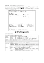
Page 84: ... function for this Switching Hub PN28248 Local Management System Main Menu Advanced Switch Configuration Menu V LAN Management L ink Aggregation Port M onitoring Configuration Rapid S panning Tree Configuration Quality of Service C onfiguration St o rm Control Configuration 802 1 X Port Based Access Control Configuration I GMP Snooping Configuration P ower Over Ethernet Configuration R RP Configur...

Page 85: ...res the storm control function settings 802 1x Port Base Access Control Configuration Configures the IEEE802 1X MAC based authentication settings IGMP Snooping Configura tion Configures the IGMP Snooping settings Power Over Ethernet Con figuration Configures the PoE power supply settings RRP Configuration Configures the ring protocol settings Loop Detection Configura tion Configures the loop detec...

Page 86: ...is a VLAN identifier attached to each frame when tagged frames are handled Also in case of untagged frames ports are divided into group by this ID and a destination of frame forwarding is determined by referring to this ID Multi ple VLAN IDs can be set to each port PVID Port VLAN ID Only one PVID can be set to each port When a untagged frame was received this ID determines to which VLAN ID the fra...

Page 87: ...nu Screen Description Total VLANs Displays the number of set VLANs Internet Mansion Displays the status of the Internet Mansion mode Enabled The Internet Mansion mode is enabled Disabled The Internet Mansion mode is disabled Factory default setting Uplink Displays the Uplink port when the Internet Mansion mode is enabled VLAN ID Displays the VLAN ID VLAN Name Displays the name of the VLAN that has...

Page 88: ...used in Internet Mansion By this setting the speci fied port becomes an Uplink port and other ports can communicate only with downlink ports Downlink ports cannot communicate with each other So it is possible to ensure security between each resident There are some constrained conditions for use Please execute configuration after confirm ing Precautions O Move to the screen to modify the VLAN setti...

Page 89: ...tion is not possible 2 Combined usage with the IGMP Snooping function is not possible 3 Combined usage with the Link Aggregation function is not possible 4 Combined usage with the Ring Redundant Protocol function is not possible 5 Registration to the MAC Address table as Static is not possible 6 The MAC Learning function in Section 4 5 8 b cannot be disabled 7 Only the Uplink port belongs to the m...

Page 90: ...LAN ID VLAN Name Port Members COMMAND Set V LAN ID Set VLAN N ame Select P ort Member A pply Q uit to previous menu Command Enter the character in square brackets to select option Fig 4 36 VLAN Creation Menu Screen Description VLAN ID Displays the VLAN ID of the VLAN you wish to create VLAN Name Displays the VLAN name of the VLAN you wish to create Port Member Displays the port number of the membe...

Page 91: ...AN name in 30 characters or less P Set the VLAN members Press P The command prompt changes to Enter egress port number Enter a port num ber When entering two or more port numbers separate them with a comma without a space or use a hyphen for consecutive numbers Q Return to the parent menu Note After configuring VLAN settings be sure to apply them by pressing A If you press Q without applying them ...

Page 92: ... VLAN ID 1 VLAN Name Port Members 1 26 Untagged Ports 1 26 COMMAND Set VLAN N ame Select P ort Member A pply Q uit to previous menu Command Enter the character in square brackets to select option Fig 4 37 VLAN Modification Menu Screen Description VLAN ID Displays the VLAN ID of the VLAN you wish to create VLAN Name Displays the VLAN name of the VLAN you wish to create Port Member Displays the port...

Page 93: ... name in 32 characters or less P Set the VLAN members Press P The command prompt changes to Enter egress port number Enter a port num ber When entering two or more port numbers separate them with a comma without a space or use a hyphen for consecutive numbers A Set the VLAN Press A to apply the created VLAN Q Return to the parent menu ...

Page 94: ...e Type P revious Page Q uit to previous menu Set Port V ID Command Enter the character in square brackets to select option Fig 4 38 VLAN Port Configuration Menu Screen Description Port Displays the port number PVID Displays the PVID Port VLAN ID that has been set to the port The PVID displays the VLAN ID to which an untagged packet should be transferred when it was received The factory default set...

Page 95: ... VLAN IDs already configured F Set the type of packets to be received 1 Press F The command prompt changes to Enter port number Enter the port num ber you wish to configure 2 Then the command prompt changes to Select port acceptable frame type A T Enter A to receive all the frames or T to receive only the tagged frames Q Return to the parent menu Note This Switching Hub can assign multiple VLANs t...

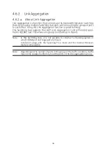
Page 96: ...ng Hub supports the LACP Link Aggregation Control Protocol speci fied in IEEE802 3ad This allows one group to include up to 8 ports Note In this Switching Hub it is not possible to construct a trunking system in which 100M port and Giga port are mixed Combined usage with the Spanning Tree mode and the Internet Mansion mode is not possible Note Depending on the number of ports in the group or the t...

Page 97: ...umber has higher priority The factory default setting is 1 Key Indicates the group number of trunking Mode Indicates the operation mode of trunking Active Sends out LACP packet from this Switching Hub and constr ucts a trunk by negotiating with other side It is required that the other side mode is Active or Passive Passive Does not send out LACP packet from this Switching Hub and constructs a trun...

Page 98: ... M The command prompt changes to Enter trunk group admin key Enter a group number you wish to modify Then the command prompt changes to LACP Active LACP Passive or Manual trunk setting A P M Enter A to make operation mode Active or P to make it Passive or M to make it Manual respectively O Set System Priority value of this Switching Hub by port in trunking Press o to open the Set Port Priority scr...

Page 99: ... The factory default setting is 1 System ID The System ID is the identifier of this Switching Hub required for constructing trunking on the network using LACP The MAC address of this Switching Hub becomes this System ID and it is not pos sible to change this ID Combination of the System Priority value and the System ID becomes the System ID in LACP Port The port number of this Switching Hub Priori...

Page 100: ...ty The factory default setting is 1 System ID The System ID is the identifier of this Switching Hub required for constructing trunking on the network using LACP The MAC address of this Switching Hub becomes this System ID and it is not pos sible to change this ID Combination of the System Priority value and the System ID becomes the System ID in LACP Key Displays the group number of trunking Aggre...

Page 101: ...101 Available commands are listed below N Display the next page Press N to display the next page P Display the previous page Press P to display the previous page Q Return to the parent menu ...

Page 102: ...COMMAND S et Monitoring Port Set Ports to be M onitored Set Traffic D irection C hange Mirror Status Q uit to previous menu Command Enter the character in square brackets to select option Fig 4 42 Port Monitoring Configuration Screen Description Monitoring Port Displays the destination port number of data for which port monitoring has been executed Be Monitored Port s Displays the port number s th...

Page 103: ...numbers delimit with comma or hyphenate the continuous numbers D Set the communication direction of the packet to be monitored Press D The command prompt changes to Select port monitoring direction R T B Enter R to monitor the receive packet T to monitor the transmit packet or B to mon itor both of the receive and transmit packets C Set the port monitoring status Press C The command prompt changes...

Page 104: ...led Protocol Version RSTP Root Port 0 Time Since Topology Change 0 Sec Root Path Cost 0 Topology Change Count 0 Designated Root 0000 000000000000 Bridge ID 0000 000000000000 Hello Time 2 Sec Bridge Hello Time 2 Sec Maximum Age 20 Sec Bridge Maximum Age 20 Sec Forward Delay 15 Sec Bridge Forward Delay 15 Sec COMMAND E nable Disable Global RSTP Set Bridge F orward Delay Set RSTP Protocol V ersion RS...

Page 105: ... uit to previous menu Command Enter the character in square brackets to select option 105 Fig 4 44 STP Mode PN28248 Local Management System Advanced Switch Configuration Rapid Spanning Tree Configuration Global RSTP Status Enabled Protocol Version RSTP Root Port 0 Time Since Topology Change xx Sec Root Path Cost 0 Topology Change Count 0 Designated Root 8000 xxxxxxxxxxxx Bridge ID 8000 xxxxxxxxxxx...

Page 106: ...he bridge ID of the root bridge Hello Time Displays the access interval with the root bridge to confirm the Spanning Tree topology Maximum Age Displays the timeout period of the hello message Forward Delay Displays the transition time of the Spanning Tree status such as from Listening to Learning or from Learning to Forwarding Bridge ID Displays the bridge ID of the Switching Hub The bridge ID is ...

Page 107: ... in the black band at the bottom of the screen F Configure the bridge forward delay Press F The command prompt changes to Enter bridge forward delay Enter a value within the range specified in the black band at the bottom of the screen B Configure the basic settings by port Press B to change to the Basic Port Configuration screen and configure the basic settings by port For the configuration metho...

Page 108: ...ost P revious Page Set Port STP S tatus Set Port Pr i ority Q uit to previous menu Command Enter the character in square brackets to select option Fig 4 46 Basic Port Configuration Screen Description Port Displays the port number Trunk Display the group number of trunk port number Link Displays the link status UP The link has been established successfully DOWN The link has not been established Sta...

Page 109: ... prompt changes to Enter priority for port Enter a number from 0 to 255 in a multiple of 16 C Set the cost of each port 1 Press C The command prompt changes to Select port number to be changed Enter the port number you wish to configure 2 Then the command prompt changes to Enter path cost for port Enter 0 to set the cost to Auto or a number from 1 to 200000000 to set a fixed cost S Enable disable ...

Page 110: ...alse False Auto False Init 10 Down Forwarding Disabled False False Auto False Init 11 Down Forwarding Disabled False False Auto False Init 12 Down Forwarding Disabled False False Auto False Init COMMAND N ext Page Set Port P t o P Status P revious Page Restart Port M igration Set Port E dge Status Q uit to previous menu Command Enter the character in square brackets to select option Fig 4 47 Advan...

Page 111: ...nd prompt changes to Select port number to be changed Enter the port number you wish to configure 2 Then the command prompt changes to Restart the protocol migration process for port Y N Press Y to restart Otherwise press N Q Return to the parent menu Admin OperEdge Displays the setting of the edge port a port that can be immediately forwarded Admin Administration displays the setting status and O...

Page 112: ...00000000000 0 0000 000000000000 00 00 10 Down 0000 000000000000 0 0000 000000000000 00 00 11 Down 0000 000000000000 0 0000 000000000000 00 00 12 Down 0000 000000000000 0 0000 000000000000 00 00 COMMAND N ext Page P revious Page Q uit to previous menu Command Enter the character in square brackets to select option Fig 4 48 Designated Topology Information Screen Description Port Displays the port nu...

Page 113: ... Command Enter the character in square brackets to select option Fig 4 49 QoS Configuration Available commands are listed below T Move to the Traffic Class configuration screen Press T The screen changes to Traffic Class Configuration Menu For the configuration contents refer to the next section 4 6 5 a E Move to the bandwidth control configuration screen Press E The screen changes to Egress Rate ...

Page 114: ...unction using IEEE802 1p Enabled QoS is enabled Disabled QoS is disabled Factory default setting Priority Displays the priority value in the VLAN tag Traffic Class Displays the priority of the Traffic Class Available commands are listed below S Enable disable the QoS function Press S The command prompt changes to Enable or Disable QoS E D Press E to enable the function Press D to disable it M Assi...

Page 115: ...duling Method Displays the scheduling method of the QoS function Strict PQ Strict priority queuing Factory default setting Weighted Round Robin WRR Weighted round robin scheduling Traffic Class Displays the priority of packets Weight Displays the weight to distribute packets Available commands are listed below S Select the scheduling method of the QoS function Press S to change the command prompt ...

Page 116: ...d 6 1000 Disabled 7 1000 Disabled 8 1000 Disabled 9 1000 Disabled 10 1000 Disabled 11 1000 Disabled 12 1000 Disabled Note Bandwidth 1Mbps unit COMMAND N ext Page Set S tatus P revious Page Q uit to previous menu Set B andwidth Command Enter the character in square brackets to select option Fig 4 52 Egress Rate Limiting Configuration Menu Screen Description Port Displays the port number Bandwidth D...

Page 117: ... g 1 3 5 26 Enter the port number to be specified 2 The command prompt changes to Enter bandwidth Enter a value from 1 to 1000 S Configure the bandwidth control settings 1 Press S The command prompt changes to Enter port number e g 1 3 5 26 Enter the port number to be specified 2 Then the command prompt changes to Enable or Disable status E D Enter E to enable the bandwidth control settings Enter ...

Page 118: ...11 0 24 0 37 0 50 0 63 0 12 0 25 0 38 0 51 0 COMMAND S et Diffserv Status Q uit to previous menu Set DSCP M apping Command Enter the character in square brackets to select option Fig 4 53 DiffServ Configuration Menu Screen Description Diffserv Status Displays the status of the DiffServ function using DSCP values Enabled DiffServ is enabled Disabled DiffServ is disabled Factory default setting DSCP...

Page 119: ...led 0 10 Disabled Disabled Disabled 0 COMMAND N ext Page Set B roadcast Status Q uit to previous menu P revious Page Set M ulticast Status Set D LF Status Set T hreshold Value Command Enter the character in square brackets to select option Fig 4 54 Storm Control Configuration Screen Description DLF Enables disables the unknown unicast storm control Enabled The unknown unicast storm control is enab...

Page 120: ...to specify 2 Then the command prompt changes to Enable or Disable broadcast storm control sta tus E D Press E to enable the broadcast storm control Press D to disable it M Enable disable the multicast storm control 1 Press M The command prompt changes to Enter port number Enter the port num ber you wish to specify 2 Then the command prompt changes to Enable or Disable multicast storm control statu...

Page 121: ...rized Transmission Period 30 seconds Supplicant Timeout 30 seconds Server Timeout 30 seconds Maximum Request 2 Quiet Period 60 seconds Re authentication Period 3600 seconds Re authentication Status Disabled Re authentication Timer Mode RADIUS COMMAND P ort No Q u iet Period Port C ontrol R e auth Period T ransmission Period Re a uth Status Supp l icant Timeout I nitialize Server Time o ut R e auth...

Page 122: ...he timeout for the client The factory default setting is 30 seconds Server Timeout Displays the timeout for the authentication server The factory default setting is 30 seconds Maximum Request The maximum number of times of retransmitting an authentication request The factory default setting is 2 Quiet Period Displays the number of seconds to wait before reattempting a failed authenti cation The fa...

Page 123: ...mpts with an integer between 1 and 10 U Set the period time to wait before reattempting a failed authentication Press U The command prompt changes to Enter Quiet Period Enter an integer between 1 and 65535 seconds X Set the maximum number of reattempts of authentication Press X The command prompt changes to Enter Max request count Enter the maxi mum number of reattempts with an integer between 1 a...

Page 124: ...able Set I G MP Snooping Status Set Report I nterval Set Static M ember Port Set M u lticast Filtering Set L eave Mode Q uit to previous menu Command Enter the character in square brackets to select option Fig 4 56 IGMP Snooping Configuration Screen Description IGMP Snooping Status Displays the IGMP Snooping function status Enabled IGMP Snooping is enabled Disabled IGMP Snooping is disabled Factor...

Page 125: ...S The command prompt changes to Enter age out time Set the time between 60 and 600 seconds I Set the Proxy Report waiting time Press I The command prompt changes to Enter forward interval Set the time between 0 and 25 seconds L Move to the Leave mode configuration screen Press L to move to the Set Leave Mode Menu screen Refer to 4 6 8 a V Move to the VLAN filter configuration screen Press V to mov...

Page 126: ...MAND N ext Page P revious Page Q uit to previous menu S et Leave Mode Set Leave Delay T ime Command Enter the character in square brackets to select option Fig 4 57 Set Leave Mode Menu Screen Description Leave Delay Time Displays the waiting time after receiving a Leave packet The factory default setting is 5 seconds Port Displays the port number Mode Displays the operation after receiving a Leave...

Page 127: ... you wish to configure 2 Then the command prompt changes to Set leave mode N I Press I to send a Leave packet to the router port immediately after receiving it Press N to wait for the specified Leave Delay Time before sending it to the router port T Set the waiting time after receiving a Leave packet Press T The command prompt changes to Set leave delay time Set the time to wait after receiving a ...

Page 128: ... VLAN Filter P revious Page Q uit to previous menu Command Enter the character in square brackets to select option Fig 4 58 VLAN Filter Configuration Screen Description VLAN ID Displays the VLAN ID Status Displays the VLAN filter status Filtered The VLAN filter is enabled Available commands are listed below N Display the next page Press N to display the next page P Display the previous page Press ...

Page 129: ...et Static Router Port Set Dynamic L earning Method Command Enter the character in square brackets to select option Fig 4 59 Router Port Table View Screen Description Dynamic Detection Displays the learning method of the router port PIM and DVMRP Learns a port that received PIM and DVMRP packets as a router port Factory default setting IGMP Query Learns a port that received IGMP Query as a router p...

Page 130: ...prompt changes to Add or Delete Static Multicast Router Port A D Press A to add a router port Press D to delete it 2 Then the command prompt changes to Enter port number Enter the port number between 1 and 26 L Specify a learning method of the router port Press L The command prompt changes to Set dynamic learning method P I B Press P for PIM DVMRP Press I for IGMP Query Press B for both Q Return t...

Page 131: ...e PoE for each port Press P to move to the PoE Port Configuration Menu screen Refer to 4 6 9 a G Configure the PoE settings Press G to move to the PoE Global Configuration Menu screen Refer to 4 6 9 b S Configure the PoE scheduler settings Press S to move to the PoE Schedule Configuration Menu screen Refer to 4 6 9 c Q Return to the parent menu Note This Switching Hub can supply power up to 185 W ...

Page 132: ...W Vol V Cur mA 1 Up NotPwr Low Auto 0 0 0 2 Up NotPwr Low Auto 0 0 0 3 Up NotPwr Low Auto 0 0 0 4 Up NotPwr Low Auto 0 0 0 5 Up NotPwr Low Auto 0 0 0 6 Up NotPwr Low Auto 0 0 0 7 Up NotPwr Low Auto 0 0 0 8 Up NotPwr Low Auto 0 0 0 9 Up NotPwr Low Auto 0 0 0 10 Up NotPwr Low Auto 0 0 0 11 Up NotPwr Low Auto 0 0 0 12 Up NotPwr Low Auto 0 0 0 COMMAND N ext Page Set PoE Port Pr i ority P revious Page ...

Page 133: ...er Power supply is stopped because the power request exceeds the limit Layer Displays the classification methods supported by the terminal device 1 Power is supplied based on Physical Layer Classification 2 Power is supplied based on Data Link Layer Classification Class Displays the class selected by the Classification function Prio Displays the priority of power supply Crit Indicates the highest ...

Page 134: ...3000 and 30000 mW in units of 200 mW As the change is applied the display on the upper screen is updated automatically If the upper limit of power supply amount is set to Auto the following values are set auto matically as limiting values of the port with combination of Layer and Class after the termi nal device is detected If the upper limit of the power supply is set to Auto the limiting value o...

Page 135: ...ration Screen Description Power Budget Displays the maximum amount of power this Switching Hub can supply Power Consump tion Displays the value of power supplied by this Switching Hub Power Usage Threshold for Sending Trap Displays the power supply threshold for sending a trap 50 is the factory default setting Power Manage ment Method Displays the power supply method when the supplied power exceed...

Page 136: ...supply power to the one newly connected Enter 1 not to supply power to the port connected next regardless of the value of priority Q Return to the parent menu Note When the power supply amount is 169 5 W or less if a IEEE802 3at compati ble PoE power receiving device that consumes power of 15 4 W or more has been newly connected and the power supply amount exceeds 185 W power supply to a port with...

Page 137: ...r Ethernet Configuration PoE Schedule Configuration Menu P ort List Configuration S chedule Configuration Q uit to previous menu Command Enter the character in square brackets to select option Fig 4 63 PoE Configuration Available commands are listed below P Set a port list Press P to move to the Port List Configuration Menu screen Refer to 4 6 9 c 1 S Set a schedule Press P to move to the Schedule...

Page 138: ...figuration Port List Configuration Menu Port List Total Entries 0 Index Port List COMMAND N ext Page D elete Port List P revious Page M odify Port List C reate Port List Q uit to previous menu Command Enter the character in square brackets to select option Fig 4 64 Port List Configuration Menu Screen Description Total Entries Displays the number of created port lists number of indexes Index Displa...

Page 139: ...t List Creation Menu screen Refer to 4 6 9 c 2 D Delete a port list Press D The command prompt changes to Enter port list index Enter the index num ber of the port list to be deleted M Modify a port list Press M The command prompt changes to Enter port list index Enter the index num ber of the port list to be modified and modify the target place in the same procedure as cre ation Q Return to the p...

Page 140: ...uare brackets to select option Fig 4 65 Port List Creation Menu Screen Description Port List Index Displays the index number of the port list Port Members Displays the port numbers that belong to the port list Available commands are listed below I Set the index number of the port list Press I The command prompt changes to Enter Port List index Enter the index number of the port number L Set a port...

Page 141: ... y Port D elete Schedule S o rting Entry Method E nable or Disable Schedule Q uit to previous menu Command PoE Schedule Configuration Port List Configuration Menu Fig 4 66 Schedule Configuration Menu Screen Description PoE Schedule Global Status Displays the PoE scheduler settings Oper status Displays the operation status of the PoE scheduler Sorting Method Displays the setting of display order By...

Page 142: ...ority Low Action Displays the number of created port lists ON Turns on the PoE OFF Turns off the PoE OFF ON Turns off the PoE and then turns it on RESTART Status Displays the PoE schedule function status by port Enable Enables the PoE schedule function by port Disable Disables the PoE schedule function by port Next Execution Time Displays the date and time on which the schedule is executed next ...

Page 143: ...es to Enable or Disable PoE Schedule index E D Enter E to enable the schedule Enter D to disable it L Display the set port list Press L The Show Port List Information Menu screen is displayed S Display the set schedule Press S The command prompt changes to Enter PoE Schedule index Enter an index number Then the Show Date List Menu screen is displayed M Edit a schedule Press M The command prompt ch...

Page 144: ...e character in square brackets to select option Fig 4 67 Create Schedule Configuration Menu Screen Description Schedule Index Displays the index number of the PoE schedule information Schedule Name Displays the name of the PoE schedule Schedule Classifier Displays the class of the PoE schedule Daily The schedule operates at the set time every day Weekly The schedule operates on the set day and tim...

Page 145: ...st Press O to move to the Date list Configuration Menu screen I Display the port list Press L The Show Port List Information Menu screen is displayed T Set the execution time Press T The command prompt changes to Enter Hour Set the hour between 0 and 23 Then the command prompt changes to Enter Minute Enter the minute between 0 and 59 L Display the port list Press L The Show Port List Information M...

Page 146: ...ule Configuration Date list Configuration Menu Total Entries 1 Date List Index Name 1 Special day COMMAND N ext Page M odify Date List P revious Page S how Date List C r eate Date List Q uit to previous menu D e lete Date List Command Enter the character in square brackets to select option Fig 4 68 Date list Configuration Menu Screen Description Total Entries Displays the number of created schedul...

Page 147: ...E The command prompt changes to Modify Date List Menu Enter the index num ber of the date list to be deleted M Modify a date list Press M The command prompt changes to Enter Date List index Enter the index num ber of the date list to be modified S Refer to a date list Press S The command prompt changes to Enter Date List index Enter the index num ber of the date list to be referred to Then the Sho...

Page 148: ...figuration Create Date List Menu Date List Index Name Year Month Day 1 2 3 4 5 6 7 8 9 10 11 12 COMMAND Set DateList I ndex Add D ate Q uit to previous menu S et Year D e lete Date Set Date List N ame A pply Schedule Command Enter the character in square brackets to select option Fig 4 69 Create Date List Menu Screen Description Index Displays the index number of the date list Name Displays the na...

Page 149: ...me Enter the name of the date list Maximum number of characters 30 D Set the date on which the date list is executed Press D The command prompt changes to Enter Date List month Enter the month between 1 and 12 Then the command prompt changes to Enter Date List days Set the date between 1 and 31 E Delete a date from the date list Press E The command prompt changes to Enter Date List month Enter the...

Page 150: ...n status Enabled The Ring Redundant Protocol function is enabled Disabled The Ring Redundant Protocol function is disabled Factory default setting Domain Name Displays the domain name Total Domain Number Displays the number of registered domains Up to 1 groups can be registered Ctrl VLAN Displays the control VLAN ID Data VLAN s Displays the data VLAN ID Ring Status Displays the ring status IDLE Th...

Page 151: ...ges to RRP Domain Modification Menu For details refer to the next section 4 6 10 b H Display the domain information Press H The command prompt changes to Enter RRP Domain Name Enter the domain name whose information you wish to view Then the screen changes to RRP Domain infor mation Menu For details refer to the next section 4 6 10 c Q Return to the parent menu Note The Ring Redundant Protocol fun...

Page 152: ...l Set F ail Period Set C ontrol VLAN Set D ata VLAN A pply Q uit to previous menu Command Enter the character in square brackets to select option Fig 4 71 RRP Domain Creation Menu Screen Description RRP Domain Name Displays the domain name RRP Node Type Displays the node role Master Indicates that the Switching Hub controls the ring operation Each domain has only one master node Transit Indicates ...

Page 153: ...nter a value between 1 and 2 seconds as the polling interval F Set the timeout for polling Press F The command prompt changes to Enter RRP Fail Period Enter a value between 2 and 5 seconds as the timeout for polling S Set the control VLAN ID Press S The command prompt changes to Enter Control VLAN ID Enter the VLAN ID 2 to 4094 you wish to set as a control VLAN When entering two or more port numbe...

Page 154: ...t Set P o lling Interval Set F ail Period Set C ontrol VLAN Set D ata VLAN A pply Q uit to previous menu Command Enter the character in square brackets to select option Fig 4 72 RRP Domain Modification Menu Screen Description RRP Domain Name Displays the domain name RRP Node Type Displays the node role Master Indicates that the Switching Hub controls the ring operation Each domain has only one mas...

Page 155: ...value between 1 and 2 seconds as the polling interval F Set the timeout for polling Press F The command prompt changes to Enter RRP Fail Period Enter a value between 2 and 5 seconds as the timeout for polling S Set the control VLAN ID Press S The command prompt changes to Enter Control VLAN ID Enter the VLAN ID 2 to 4094 you wish to set as a control VLAN When entering two or more port numbers sep ...

Page 156: ...he domain name Node Type Displays the node role Master Indicates that the Switching Hub controls the ring operation Each domain has only one master node Transit Indicates that the Switching Hub is not a master node Ring Status Displays the ring status IDLE The Ring Redundant Protocol function is disabled Complete The ring topology has been correctly established This status is displayed for the Mas...

Page 157: ...Port Displays the secondary port Secondary Port Status Displays the secondary port status Unknown The domain is disabled Forwarding Normal communication is executed Down The port does not link up Blocking No frames other than control frames are not received Secondary Port Role Displays the secondary port role Upstream Operating as an upstream port Downstream Operating as a downstream port Polling ...

Page 158: ...abled Enabled 60 12 Down Forwarding Enabled Enabled 60 COMMAND N ext Page Set Port L oop Detect Status P revious Page Set Port Recovery S tatus E nable Disable Loop Detection Set Port Recovery T imer Loop History I nformation Q uit to previous menu Command Enter the character in square brackets to select option Fig 4 74 Loop Detection Configuration Menu Screen Description Global Loop Detec tion St...

Page 159: ...x E D Press E to enable the automatic port recovery Press D to disable it When entering multiple port numbers delimit with comma or hyphenate the continuous numbers To configure all ports enter 0 as the port number T Display the Recovery Time seconds that is a waiting time until a port starts to be automatically recovered after being blocked 1 Press T The command prompt changes to Select port numb...

Page 160: ...ption Fig 4 75 Loop History Information View Screen Description Entry Displays the event number Time Displays the time when the event occurred or the time accumulated after boot if the clock is not set Event Displays the description of the event caused to the Switching Hub The loop detected on portX A loop was detected and connection was blocked on a Switching Hub in Port X The loop detected betwe...

Page 161: ...ower Limit Set B ias Current Limit Set Limit Trap S tatus Set V oltage Limit Q uit to previous menu Command Enter the character in square brackets to select option Fig 4 76 IGMP Snooping Configuration Screen Description Limit Trap Status Displays the trap sending settings for change state SFP Port Number Displays the port to insert SFP modules Tranceiver Type Displays the type of SFP modules Vende...

Page 162: ...nter value please enter the value V Configure the threshold of voltage Press V The command prompt changes to Auto or Manual A M Press A to set the information of SFP modules automatically Press M to set it manually The command prompt changes to High or Low H L Press H to set the upper Press L to set the lower The command prompt changes to Alarm or Warning A W Press A to set the alarm Press w to se...

Page 163: ...s S elect Port Re f resh Mode Since R eset Q uit Command Enter the character in square brackets to select option Fig 4 77 Statistics Values Accumulated after Reboot Screen Description Port Displays the port number Refresh Displays the refresh interval The factory default setting is 300 seconds Elapsed Time Since System Up Displays this Switching Hub s reboot time Counter Name Displays each counter...

Page 164: ...et Since U p Q uit Command Enter the character in square brackets to select option Fig 4 78 Display of Values Accumulated after Resetting the Counters Screen Description Port Displays the port number Refresh Displays the refresh interval The factory default setting is 300 seconds Elapsed Time Since System Reset Displays the time elapsed since resetting of the counters Counter Name Displays each co...

Page 165: ...ign Errors Displays the number of error packets that have a normal packet length 64 to 1518 bytes however have an error found by an error detection code FCS If the packet length is an integral multiple of one byte the error is a CRC FCS error If not it is an alignment error Undersize Pkts Displays the number of error packets that have a packet length less than 64 bytes however have no other errors...

Page 166: ...166 Note This screen is set to refresh at the refresh intervals Therefore if the timeouts of the console SSH and Telnet are set to be longer than the refresh interval timeouts do not occur ...

Page 167: ...menu Command Enter the character in square brackets to select option Fig 4 79 Switch Tools Configuration Screen Description TFTP Software Upgrade Configures and executes firmware upgrade of this Switching Hub Configuration File Upload Download Configures and executes upload download of the configuration of this Switching Hub System Reboot Configures and executes reboot of this Switching Hub Except...

Page 168: ...server with the firmware to be upgraded installed Image File Name Displays the file name of the firmware to be upgraded Reboot Timer Displays the time before booting after downloading the firmware You can set the time in System Reboot Menu Available commands are listed below S Set the IP address of the TFTP server with the firmware to be upgraded installed Press S The command prompt changes to Ent...

Page 169: ...set by Reboot Timer PN28248 Local Management System Software Upgrade Menu Download Status TFTP Server IP 192 168 1 100 Image File Name pn28248 rom Protocol TFTP Press CTRL C to quit downloading Data received Bytes 125952 Fig 4 81 Download in Process Note After the download completes the black band at the bottom of the screen displays System will reset automatically after image program into flash W...

Page 170: ...h Tools Configuration Configuration File Upload Download TFTP Server IP 0 0 0 0 Config File Name COMMAND Set TFTP S erver IP Address Set Configuration F ile Name U pload Configuration File D ownload Configuration File Q uit to previous menu Command Enter the character in square brackets to select option Fig 4 82 Configuration File Upload Download Screen Description TFTP Server IP Displays the IP a...

Page 171: ...ers or less U Start the upload of the configuration file Press U The command prompt changes to Upload file Y N Confirm whether or not you wish to start the process Confirm that all settings are correct Press Y to start the pro cess If you have find an error in settings press N to return to the original status D Start the download of the configuration file Press D The command prompt changes to Down...

Page 172: ...ys whether or not the reboot command is executed Stop Displays that the reboot command is not executed In Process Reboot in process or in waiting status set by the reboot timer Reboot Type Displays the reboot type The factory default setting is Normal Normal Normal reboot is executed Factory Default All settings are reset to factory default Factory Default Except IP All settings except the IP addr...

Page 173: ...actory default or I to save only the IP address setting and return the other settings to factory default R Execute the reboot Press R The command prompt changes to Are you sure to reboot the system Y N Press Y to execute it Press N to cancel it T Set the time before the system is rebooted Press T The command prompt changes to Enter Reboot Timer Enter a value between 0 and 86400 seconds 24 hours Q ...

Page 174: ...ckets to select option Fig 4 84 Exception Handler Configuration Screen Description Exception Handler Displays the exception handling function status Disabled is the factory default setting Enabled The exception handler is enabled Disabled The exception handler is disabled Exception Handler Mode Displays the exception handling method Debug Message is the factory default setting Debug Message Output...

Page 175: ...tion Press D to disable it M Set the exception handling method Press M The command prompt changes to Select Exception Handler Mode M R B Press M to display the debug message R to reboot or B to execute both M Set the exception handling method Press M The command prompt changes to Select Exception Handler Mode M R Press M to display the debug message or R to reboot Q Return to the parent menu ...

Page 176: ...10 Timeout Value 3 Sec Result COMMAND Set Target I P Address E xecute Ping Set N umber of Requests S top Ping Set T imeout Value Q uit to previous menu Command Enter the character in square brackets to select option Fig 4 85 Ping Execution Screen Description Target IP Address Displays the IP address of the target of the ping The factory default setting is 0 0 0 0 Number of Request Displays the num...

Page 177: ...he display Press E The command prompt changes to Execute Ping or Clean before Ping Data E C Press E to execute ping Press C to only clear the display S Cancel the ping command Press S or Ctrl C during the ping execution to cancel it Q Return to the parent menu PN28248 Local Management System Switch Tools Configuration Ping Execution Target IP Address 192 168 1 100 Number of Requests 10 Timeout Val...

Page 178: ... the character in square brackets to select option Fig 4 87 System Log Each event displayed on this screen links to an SNMP trap Events for which a trap is set to be sent are displayed The relationships with traps are shown below Screen Description Entry Displays the event number Time Displays the time when the event occurred or the time accumulated after boot if the clock is not set Event Display...

Page 179: ...xx xx xx xx was authorized at port xx Indicates that IEEE802 1X authentication succeeded on Port xx from the terminal with xx xx xx xx xx xx xx xx xx xx xx xx was rejected at port xx Indicates that IEEE802 1X authentication failed on Port xx from the ter minal with xx xx xx xx xx xx Authentication failure Indicates that an unauthorized manager accessed by SNMP Port xx Power ON notifica tion Indica...

Page 180: ...isplayed for the Transit nodes only DDM Rx power Tx power Temperature Volt age Bias current is exceeded fell high low alarm warn ing on Portx Indicates that SFP module status was changed Rx power Indicates that SFP Rx power status was changed Tx power Indicates that SFP Tx status was changed Temperature Indicates that SFP temperature status was changed Voltage Indicates that SFP voltage status was...

Page 181: ...yslog when the link status changes Enabled Enable of save syslog Factory default Disabled Disable of save syslog PoE PN OFF Display the configure of enable disable the save syslog when the PoE supply sta tus changes Enabled Enable of save syslog Factory default Disabled Disable of save syslog Available commands are listed below L Configure of enable disable the save syslog when the link status cha...

Page 182: ...er Q uit to previous menu Command Enter the character in square brackets to select option Fig 4 89 Watch Dog Timer Menu Screen Description Watch Dog Timer Displays the Watch Dog Timer function status Disabled is the factory default setting Enabled The function is enabled Disabled The function is disabled Available commands are listed below W Switch the Watch Dog Timer function status Press W The c...

Page 183: ...reen the command prompt changes to Save current configuration Y N Press Y to save the configuration Otherwise press N If you don t save the configuration it will be deleted when the system is rebooted or the power is shut down PN28248 Local Management System Main Menu Save Configuration to Flash Save current configuration Y N Y for Yes N for No Fig 4 90 Save Configuration to Flash Screen Confirm W...

Page 184: ...PN28248 Local Management System Main Menu Save Configuration to Flash Saving configuration to flash is successful press any key to continue 184 Fig 4 91 Save Configuration to Flash Screen Completed ...

Page 185: ... in Fig 4 92 On this screen you can use the command line for configuration instead of the menu Refer to the separate volume Operation Manual For CLI for configura tion procedures Enter logout at the command prompt to return to the Menu from CLI M24eGLPWR Fig 4 92 Command Line Interface CLI ...

Page 186: ...ou access using Telnet or SSH then pressing Q terminates the connection Follow the login procedures shown in Section 4 1 of Basic Operation Manual to log in again You are automatically logged out after the time set in the timeout field shown in section Section 4 5 7 System Security Configuration has elapsed ...

Page 187: ...le 8K entries unit Buffered memory 512KB unit Flow control IEEE802 3x full duplex Back pressure half duplex Major functions IEEE802 1D Spanning Tree Protocol IEEE802 1w Rapid Spanning Tree Protocol IEEE802 1Q Tag VLAN 256 VLANs max IEEE802 3ad Link aggregation Capable of establishing up to eight ports in eight groups IEEE802 1p QoS function Four levels of Priority Queue supported IEEE802 1X Port b...

Page 188: ...groups Power Ethernet MIB RFC 3621 Note pethPsePortPowerPriority not supported Power supply specifications Power supply AC 100 240 V 50 60 Hz 4 5 A Power consumption Normally Max 248 W Min 17 4 W Environment specifications Operating temperature 0 to 50 degrees C Operating humidity 20 to 80 RH no condensation Storage temperature 20 to 70 degrees C Storage humidity 10 to 90 RH no condensation Extern...

Page 189: ...l included in ZEQUO assist archive file for more detail 1 Upzip the archive file ZEQUOASSIST_vxxxx zip include in attached CD ROM 2 Run ZEQUOASSIST exe and set login ID and password for this application 3 Click The MNO series button in the ZEQUO assist Launcher 4 Click Terminal Emulator button in the ZEQUO assist main window 5 Check Console in Terminal emulator connection method field and choose t...

Page 190: ...igured only with the software Easy Config In the software the item is displayed as Camera name Restrictions The time for accepting setting changes is limited to 20 minutes after power on to ensure security However you can change settings regardless of the time limit if the IP address subnet mask default gateway user name and password values are set to factory defaults Even after the time limit is ...

Page 191: ...user directly uses If you connect a hub that does not support the Loop detection and blocking func tion to a downstream switch and a loop failure occurs in the switch the down stream switch port that caused a loop is blocked to prevent a loop failure from affecting the entire network Upstream switch Downstream switch 1 Downstream switch 2 Hub not support ing Loop detec tion and blocking function P...

Page 192: ... be disabled on the upstream switch Then network configuration and switch settings need to be changed to block only the port having a loop on the switch Upstream switch Downstream switch 1 Downstream switch 2 PC 1 PC 2 PC 3 1 4 3 2 Occurrence conditions 1 Communication is taking place between PC 1 and PC 2 and between PC 1 and PC 3 2 A loop occurs on downstream switch 2 3 The upstream switch detec...

Page 193: ...rminal settings The Port LED Left lights in failed Check the port settings of this Switching Hub or the terminal settings LOOP HISTORY LED Blinks in green This is no notify that there is a port in which a loop is occurring or has been removed within 3 days Communications are slow Are the communication speed and mode settings correct If the proper communication mode signal cannot be obtained apply ...

Page 194: ...s the Powered Device connected to the port compliant with the IEEE802 3at 30W standard Port LED right is blinking orange Ensure that the total power supply demand from PoE powered devices does not exceed 185 W When the power supply is suddenly shut off It is likely that a PoE powered device in use has a different power consump tion in normal operation and standby states After turning on the PoE LE...

Page 195: ...nual please use the Memo shown on the next page and make a repair request with the following information to your dealer Product name Model number Product serial number an 11 digit number attached on the back of the main unit Firmware version The number after Ver labeled on the unit package Problem status Please give as concrete information as possible Within the warranty period Repair service will...

Page 196: ...11 digit number labeled on the product Store dealer Tel Customer service contact Tel Check screen is described in Section 4 4 of the Operation Manual Menu Interface Panasonic Eco Solutions Networks Co Ltd 2015 2016 Panasonic Eco Solutions Networks Co Ltd 2 12 7 Higashi Shimbashi Minato ku Tokyo Japan 105 0021 URL http panasonic co jp es pesnw english P0615 3086 ...

Reviews: