39
English
Installing the Receiver
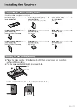
Components for receiver mounting bracket
Check the following parts are included.
Base bracket (A-1) ........................1
(DPVF3503ZA/X1)
Connecting bracket C (A-4)
.........1
(DPVF3506ZA/X1)
Used to install on the projector.
Knurled screw (C-1)......................2
(DPVF3509ZA/X)
(M4×5)
Connecting bracket A (A-2) .........1
(DPVF3505ZA/X1)
Used to install on the display.
Sheet A (B-1) .................................1
(DPVF3507ZA/X1)
(30×12 mm)
Screw (C-2) ....................................6
(DPVF3510ZA/X1)
(M4×5)
Connecting bracket B (A-3) .........1
(DPVF3504ZA/X1)
Used to install on the display.
Sheet B (B-2) .................................3
(DPVF3508ZA/X1)
(24×20 mm)
Screw (C-3) ....................................2
(DPVF3511ZA/X1)
(M3×8)
Mounting the base bracket (common)
1
Place the base bracket (A-1) aligning it with the 4 screw holes on the bottom
surface of the receiver.
2
Fix the base bracket (A-1) with 4 screws (C-2).
C-2
A-1
The base bracket can be mounted in either vertical or horizontal direction.


