background image

56

PAW-VP•LDHW - Technical Manual – 2020-07

System drawings

6

6.2  System PACi/ECOi DHW

(Field supplied) accessories 

Pressure control valve if inlet city water is 

more than 6 bar (field supplied)*

Strainer (field supplied)*

Expansion tank if check valve or pressure 

control valve is mounted (field supplied)*

Circulation water pump (e.g. Grundfos 

comfort UP 15–14 BA PM, field supplied)

Safety valve 6 or 9.5 bar (field supplied)**

Temperature control valve (field supplied)

Water pipe inlet/outlet VP1000L/750 

(35 mm) VP500L/200 (22 mm)

PAW-VP-RTC5B-PAC/VRF controller

For a hotel or apartment complex where the last room is more than 30 meters away from the 

DHW tank, a water pump (for example type Grundfos comfort UP 15-14 BA PM) should be 

installed in order to obtain hot water quickly.
Remember to install a return pipe for pump circulation of maximum Ø15 mm and make sure that 

supply and return pipes are well insulated to minimise heat loss.

  Standard system 

with circulation pipe and 

temperature control system

DHW

City Water in

Ø15 mm max.

1

2

3

8

7

7

6

5

4

*  This is supplied in UK as part of optional accessory (PAW-G3KITL).

**  For models PAW-750LDHW-1 and PAW-1000LDHW-1. The pressure temperature relief valve is factory 

fitted as standard.

Summary of Contents for PRO-HT Tank Series

Page 1: ...scale Trusted quality Double tube heat exchanger following drinking water regulation Tank and heat exchanger made with stainless steel Internal and external pickling One by one system compatible list...

Page 2: ...ominal electrical power kW 5 12 6 14 Reference tapping cycle 2XL 2XL Energy consumption by chosen cycle A7 W10 55 kWh 4 14 5 10 Energy consumption by chosen cycle A15 W10 55 kWh 3 50 4 61 COP DHW A7 W...

Page 3: ...01218 2 Commercial System Air Conditioner Air to Water Heat Pump Systems PAW VP1000LDHW PAW VP750LDHW PAW VP380L Domestic Hot Water and Heating and Cooling Systems for R410A and R32 Use Technical Manu...

Page 4: ......

Page 5: ...opyright of this manual remains with the manufacturer No part of this manual may be reproduced in any form or processed duplicated or distributed using electronic systems without the written permissio...

Page 6: ...L 26 1 1 5 PAW VP RTC5B PAC PAW VP RTC5B VRF 27 1 3 Main components 28 1 3 1 Tank models PAW VP1000L 750L 28 1 3 2 Tank model PAW VP380L 29 1 4 Main components PAW VP RTC5B PAC 30 1 5 Main components...

Page 7: ...on 47 4 1 Tank unit refrigerant piping installation 47 4 2 DHW tank water quality 47 4 3 DHW tank unit installation space 48 4 4 Filling procedure 49 4 5 Emptying procedure 49 4 6 Maintenance procedur...

Page 8: ...VP RTC5B VRF 72 8 Connecting the Refrigerant Tubing 73 8 1 Use soldering method 73 8 2 Preparation of cooling pipe for tank 73 8 3 How to install the expansion valve when using ECOi 73 8 4 Installatio...

Page 9: ...n of the Heating Unit 94 11 2 2Electrical Connection 95 11 3 Start up and Service 96 11 3 1Operation Keys and Displays 96 11 3 2Menu diagram 98 11 3 3Operational Menu 99 11 3 4Service Menu 99 11 4 Che...

Page 10: ...ual Target groups This manual is intended for specialist planners and installers as well as service companies Installation commissioning and maintenance of the products may only be carried out by qual...

Page 11: ...ard or unsafe practice which can result in severe personal injury or death Follow the warnings provided to avoid this CAUTION This symbol refers to a hazard or unsafe practice which can result in pers...

Page 12: ...ult of a sequence of work steps indicates an enumeration Key indicates the name of a key Option indicates an option of the panel Menu Option indicates a sequence of several options that must be select...

Page 13: ...on notices given in this manual DANGER This symbol refers to a hazard or unsafe practice which can result in severe personal injury or death Follow the warnings provided to avoid this CAUTION This sym...

Page 14: ...exclusively for each unit and full disconnection means with contact separation in all poles must be incorporated in the fixed wiring in accord ance with the wiring rules To prevent possible hazards f...

Page 15: ...ndation for the outdoor unit This prevents water damage and abnormal vibration In an area with high winds Securely anchor the outdoor unit down with bolts and or a metal frame Provide a suitable air b...

Page 16: ...leaks A halide torch or any other detector using a naked flame shall not be used Electronic leak detectors may be used to detect refrigerant leaks but the sensitivity may not be adequate or may need r...

Page 17: ...not repair by yourself Contact the sales dealer or service dealer for repair CAUTION Do not touch the air inlet or the sharp aluminum fins of the outdoor unit You may get injured Ventilate any enclose...

Page 18: ...on the refrigerant charge label supplied with the product a b c 1000 CO2 equivalent in tons multiply the total refrigerant charge by GWP value then divided by 1000 The filled out label must be adhered...

Page 19: ...xceed a set limit The refrigerant R410A which is used in the air conditioner is safe without the toxicity or com bustibility of ammonia and is not restricted by laws imposed to protect the ozone layer...

Page 20: ...ere is an effective opening with the adjacent room for ventilation of leaking refrigerant gas opening without a door or an opening 0 15 or larger than the respective floor spaces at the top or bottom...

Page 21: ...70 80 90 100 kg m m 85 80 75 70 65 60 55 50 45 40 35 30 25 20 15 10 5 0 229 5 216 0 202 5 189 0 175 5 162 0 148 5 135 0 121 5 108 0 94 5 81 0 67 5 54 0 40 5 27 0 13 5 0 0 Total amount of refrigerant M...

Page 22: ...consumption with heater W 18900 Number of electrical heaters power W 1 6000 Voltage frequency V Hz 400 50 Electric protection heater A 16 Moisture protection IP24 Domestic hot water preparation Heatin...

Page 23: ...of electrical heaters power W 1 6000 Voltage frequency V Hz 400 50 Electric protection heater A 16 Moisture protection IP24 Domestic hot water preparation Heating with heat pump Min Max C 5 65 Heating...

Page 24: ...10A Refrigerant at shipment kg 8 3 8 3 Outdoor ambient operating range C 20 24 20 24 Heating up time min 162 133 VP tank DHW Stainless steel 316L pickling protective magnesium anode Average insulation...

Page 25: ...ction 1 1 4 Heating water flow T 5K 35 C m h 3 9 Capacity of integrated electrical heater kW Not equipped Flow switch Not equipped Water filter Not equipped Input power kW 0 012 Maximum current A 0 05...

Page 26: ...al Data of Indoor Unit 1 1 2 Outlines and dimensions 1 2 1 Tank model PAW VP1000LDHW 2210 1846 427 0 276 1275 170 990 Rp 1 1 4 1 2 Rp 1 1 4 3 4 1 2 1475 1 1 4 Rp 1 630 R 2090 All dimensions in mm i No...

Page 27: ...020 07 Technical Data of Indoor Unit 1 1 2 2 Tank model PAW VP750LDHW 1855 1426 427 0 270 1085 170 990 Rp 1 1 4 1 2 Rp 1 1 4 3 4 1 2 1305 1 1 4 Rp 1 630 R 2090 All dimensions in mm i Note R value indi...

Page 28: ...HW Technical Manual 2020 07 Technical Data of Indoor Unit 1 1 2 3 Tank model PAW VP380L 2 5 BAR 1750 690 7 8 1 2 1510 245 0 585 R 1900 1820 All dimensions in mm i Note R value indicates maximum overtu...

Page 29: ...Manual 2020 07 Technical Data of Indoor Unit 1 1 1 5 PAW VP RTC5B PAC PAW VP RTC5B VRF mounting holes 348 mounting holes 128 6 9 3 10 93 5 360 359 160 159 1 4 4 75 25 4 100 1 5 3 5 120 23 23 5 5 9 83...

Page 30: ...or D Adjustable levelling feet E Inlet city water 1 1 4 F Booster heater 6 kW G Return pump circulation 1 2 H Magnesium anode I Outlet DHW 1 1 4 J Sensor pocket TA K Safety valve 1 L Hot gas sensor E3...

Page 31: ...2 C Turn waterborne heating 1 1 4 D Booster heater 6 kW E Return waterborne heating F Safety valve 3 bar G Adjustable levelling feet H Liquid sensor E1 and E2 I Sensor pocket TA J Hot gas sensor E3 F...

Page 32: ...ture sensor TA D Temperature sensor E1 E Temperature sensor E2 included in delivery 1 5 Main components PAW VP RTC5B VRF A F B C D E A PAW VP RTC5B VRF B CZ RTC5B C Temperature sensor BL D Temperature...

Page 33: ...ling area This is expected to result in a layering of temperatures See example 1000ltr DHW tank Set point position of TA temperature sensor ON OFF Set point Low part tank Middle part tank Upper part t...

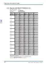
Page 34: ...ated from 10 C to 50 C at an ambient temperature of 7 C The heat ing phase takes 3 23 47h Without tapping In practice the cycle described above is valid during commissioning If system design in ac cor...

Page 35: ...27 10 71 3 57 50 C 3 23 47 44 34 13 55 3 27 55 C 4 08 34 48 38 16 53 2 93 2 C 45 C 3 08 53 38 27 12 56 3 05 50 C 3 58 58 44 34 15 89 2 79 55 C 4 51 29 48 38 19 38 2 50 0 C 45 C 3 10 40 38 27 12 68 3...

Page 36: ...C 3 17 12 42 16 13 11 3 22 55 C 4 01 59 46 20 16 09 2 87 2 C 45 C 3 01 10 36 08 12 05 3 00 50 C 3 51 15 42 16 15 38 2 74 55 C 4 43 46 46 20 18 87 2 45 0 C 45 C 3 02 53 36 08 12 16 2 97 50 C 3 53 27 42...

Page 37: ...3 09 18 38 89 12 59 3 09 55 C 3 54 05 42 93 15 57 2 76 2 C 45 C 2 51 54 32 82 11 43 2 87 50 C 3 41 59 38 89 14 76 2 63 55 C 4 34 30 42 93 18 25 2 35 0 C 45 C 2 53 32 32 82 11 54 2 84 50 C 3 44 06 38...

Page 38: ...3 04 49 35 67 12 29 2 90 55 C 3 49 36 39 71 15 27 2 60 2 C 45 C 2 46 38 29 59 11 08 2 67 50 C 3 36 44 35 67 14 41 2 47 55 C 4 29 15 39 71 17 91 2 22 0 C 45 C 2 48 14 29 59 11 19 2 65 50 C 3 38 48 35 6...

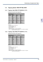
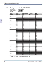
Page 39: ...ng Heating the water from 10 C to end temperature Please note The data mentioned in this document is obtained by calculation Please use only for reference 3 2 2 Tapping table PAW VP1000LDHW 12 C Tappi...

Page 40: ...ter from 15 C to end temperature Please note The data mentioned in this document is obtained by calculation Please use only for reference 3 2 4 Tapping table PAW VP1000LDHW 18 C Tapping amount with en...

Page 41: ...29 69 10 16 2 92 50 C 3 12 57 34 40 12 83 2 68 55 C 3 55 00 37 53 1 63 2 40 2 C 45 C 2 59 15 29 69 11 92 2 49 50 C 3 46 16 34 40 15 05 2 90 55 C 4 35 35 37 53 18 33 2 05 0 C 45 C 3 00 57 29 69 12 03...

Page 42: ...3 06 36 32 71 12 41 2 64 55 C 3 48 39 35 84 15 20 2 36 2 C 45 C 2 51 48 28 00 11 42 2 45 50 C 3 38 49 32 71 14 55 2 25 55 C 4 28 08 35 84 17 83 2 01 0 C 45 C 2 53 26 28 00 11 53 2 43 50 C 3 40 54 32 7...

Page 43: ...59 11 30 17 11 92 2 53 55 C 3 41 14 33 30 14 71 2 26 2 C 45 C 2 43 06 25 46 10 85 2 35 50 C 3 30 08 30 17 13 97 2 16 55 C 4 19 26 33 30 17 25 1 93 0 C 45 C 2 44 39 25 46 1 95 2 33 50 C 3 32 07 30 17...

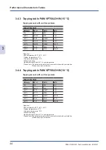
Page 44: ...54 59 27 67 11 64 2 38 55 C 3 37 01 30 81 14 43 2 13 2 C 45 C 2 38 10 22 96 10 52 2 08 50 C 3 25 12 27 67 13 65 2 03 55 C 4 14 30 30 81 16 92 1 82 0 C 45 C 2 39 40 22 96 10 62 2 16 50 C 3 27 09 27 67...

Page 45: ...ng Heating the water from 10 C to end temperature Please note The data mentioned in this document is obtained by calculation Please use only for reference 3 4 2 Tapping table PAW VP750LDHW 12 C Tappin...

Page 46: ...ter from 15 C to end temperature Please note The data mentioned in this document is obtained by calculation Please use only for reference 3 4 4 Tapping table PAW VP750LDHW 18 C Tapping amount with end...

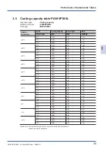
Page 47: ...94 12 C 22 80 7 70 2 96 25 C 5 C 12 54 5 05 2 48 7 C 14 37 5 98 2 40 12 C 23 00 6 30 3 65 20 C 5 C 13 21 4 88 2 71 7 C 15 14 5 73 2 64 12 C 23 40 6 11 3 83 15 C 5 C 12 15 4 80 2 53 12 C 13 92 5 64 2 4...

Page 48: ...4 40 7 27 3 36 45 C 23 90 7 72 3 10 50 C 21 28 8 28 2 57 7 C 35 C 25 00 7 03 3 56 40 C 24 20 7 23 3 35 45 C 23 70 7 23 3 28 50 C 21 08 8 24 2 56 2 C 35 C 23 00 6 94 3 31 40 C 22 20 7 14 3 11 45 C 21 7...

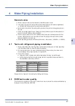
Page 49: ...Water operating pressures DHW tank Minimum Maximum 0 05 MPa 0 95 MPa 4 1 Tank unit refrigerant piping installation 1 Please make flare after inserting flare nut located at joint portion of tube assemb...

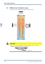
Page 50: ...n space The DHW tank must be installed with the following maintenance space 350 mm or more 400 mm or more 100 mm or more CAUTION The tank level must be adjusted before the piping installation can star...

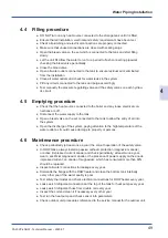
Page 51: ...y to the tank Open a bleed valve on the set connected to the tank to allow the entry of air into the system Open the discharge of the system paying attention to the high temperature of the water outle...

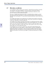
Page 52: ...inted on the label of the tank This term does not extend if it is renewed as a result of an intervention of warranty replacement The warranty period is shown on the label of each product For accessori...

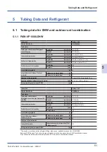
Page 53: ...ed additional refrigerant over 7 5 meters g m 45 7 5m 1400 g 45 g m Refrigerant charged at shipment R410A kg 6 4 Indoor Unit Outdoor Unit PAW VP1000LDHW U 16MF3E8 Tubing data Tubing size outer diamete...

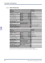
Page 54: ...er 7 5 meters g m 45 7 5m 1200 g 45 g m Refrigerant charged at shipment R410A kg 6 4 Indoor Unit Outdoor Unit PAW VP750LDHW U 16MF3E8 Tubing data Tubing size outer diameter Refrigerant connection pipe...

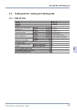
Page 55: ...m inch brazing 12 7 1 2 Gas tube mm inch brazing 19 05 3 4 Outdoor unit pipe junction Liquid tube mm inch flared connection 9 52 3 8 Gas tube mm inch flared connection 25 4 1 Adapter Wall thickness of...

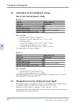
Page 56: ...remove is 837 g Example 2 Indoor Unit PAW VP1000LDHW Outdoor unit U 250PE2E8A Pre charge kg 6 4 Total pipe length one way m 5 Attention follow instruction g Remove 1400 g for pipe length 7 5 m Require...

Page 57: ...OFF 80 min Through the day ON 15 min OFF 40 min For a hotel or apartment complex where the last room is more than 30 meters away from the DHW tank a water pump for example type Grundfos comfort UP 15...

Page 58: ...L 200 22 mm H PAW VP RTC5B PAC VRF controller For a hotel or apartment complex where the last room is more than 30 meters away from the DHW tank a water pump for example type Grundfos comfort UP 15 14...

Page 59: ...e kit 1 Port 2 x CZ P160HR3 Two kits are required for PAW VP1000LDHW or PAW VP750LDHW Accessories must be ordered separately Solenoid valve kit 4 Port CZ P4160HR3 Two ports are required for PAW VP1000...

Page 60: ...PAW VP750LDHW Accessories must be ordered separately The discharge pipe must be kept as short as possible max 50 m to the DHW tank and con nected at the first branch of the outdoor unit The pressure...

Page 61: ...lied F Temperature control valve field supplied G Water pipe inlet outlet VP1000L 750 35 mm H Expansion valve PAW VP VALV 280 op tional accessory I BL sensor J E2 sensor K E1 sensor L E3 sensor M Sole...

Page 62: ...be used for heating and cooling Remember to always install pressure balancing valve for outlet water for equal water flow Water circulation can be increased or decreased for the desired temperature d...

Page 63: ...water flow DN35 field supplied D Water pipe main return turn 52 mm field supplied E Max water flow 8000 L h F TA sensor H E1 sensor I E2 sensor J Air separator field supplied K PAW VP RTC5B PAC contro...

Page 64: ...that occurs as a result of such unauthorized changes 7 Regulations on wire diameters differ from locality to locality For field wiring rules please refer to your LOCAL ELECTRICAL CODES before commenci...

Page 65: ...g PAW RTC5B PAC VRF Single phase 220 230 240 V 1 00 mm2 2 A Power supply cable backup heater Model name Power supply Minimum power supply cables L1 N PE Circuit breaker Min recommended rating PAW VP75...

Page 66: ...ch as H05RN F or H07RN F which conform to CENELEC HAR rating specifications or use the cables based on IEC standard 60245 IEC57 60245 IEC66 Refer to 7 2 Recommended Wire Diameter for recommended minim...

Page 67: ...2020 07 Electrical Wiring 7 7 3 Indoor unit Electric Wiring Diagrams only VRF 7 3 1 Wiring system diagram for EX valve magnetic coil PAW VP VALV 280 5 4 3 2 1 OG RD YE BK GR OG RD YE BK GR Terminal RT...

Page 68: ...E2 Condensing temperature thermistor Heat exchanger outlet heating mode E3 Water outlet temperature thermistor Water outlet BL Water inlet temperature thermistor Water inlet Optional to be purchased...

Page 69: ...de E2 Condensing temperature thermistor Heat exchanger outlet heating mode E3 Water outlet temperature thermistor Water outlet BL Water inlet temperature thermistor Water inlet Optional to be purchase...

Page 70: ...emperature thermistor Heat exchanger inlet heating mode BL Set temperature thermistor Middle Tank Optional to be purchased separately for monitoring only TA Only us for water inlet CV 623 321 0025 E2...

Page 71: ...nnect wiring to the terminal Proceed as follows 1 A screwdriver is inserted with a rocking motion to the stop 2 The screwdriver is captivated holding the CAGE CLAMP open while the wire is inserted 3 T...

Page 72: ...E2 E2 and connect the sensor E2 Terminal PAW VP RTC5B VRF Important When using PAW VP RTC5B VRF together with ECOi MF3 DHW tank and air to air indoor unit remember to install adapter CZ CAPE2 for sol...

Page 73: ...with a downwards running U shaped loop Hold the temperature sensor so that the measuring tip points upwards Let the control cable of the temperature sensor hang loosely insert the tip of the temperatu...

Page 74: ...C 7 4 5 How to use with Terminal PAW VP RTC5B VRF E2 E1 BL optional E3 optional E3 optional BL optional PAW VP1000LDHW PAW VP750LDHW PAW VP380L E1 E2 TA TA PAW VP RTC5B PAC PAW VP RTC5B PAC E2 optiona...

Page 75: ...air conditioners employ the flaring method to connect refrig erant tubes which run between indoor and outdoor units In this method the copper tubes are soldering at tank end WARNING Remember to cool...

Page 76: ...15 CAUTION Remember to cool down pipes with wet paper during soldering When installing the expansion valve the following limitations and restrictions need to be observed The distance from tank heat e...

Page 77: ...Keep pressing the and buttons simultaneously for 4 or more seconds The Maintenance func screen appears on the LCD display Maintenance func Sel Page 20 30 THU Confirm 1 Outdoor unit error data 2 Servic...

Page 78: ...button or keeping it pressed 4 Select the Set data by pressing the or button Select one of the Set data by pressing the or button Then press the button 5 Select the Unit no by pressing the or button...

Page 79: ...group control item code 10 and settings data 00XX are displayed blinking on the remote controller LCD dis play see figure below At this time the indoor unit fan or all indoor unit fans in the case of...

Page 80: ...e 3 Press the timer time buttons to select the desired setting data For item codes and setting data refer to sec 9 1 6 DN code setting list on page 80 4 Press the button The display stops blinking and...

Page 81: ...ibed at pages before Setting Procedure for Remote Controller Mode CZ RTC5B See corresponding DN code list described on the following pages combination for combination for Indoor Unit 6 7 Described at...

Page 82: ...n display 0d 0000 0001 Cool Heat auto non active 15 0022 0013 16 0000 0000 Fan speed not displayed 21 0030 0055 Heating upper limit 55 C 22 0018 0035 Heating lower limit 35 C 28 0001 0001 Automatic re...

Page 83: ...ng preparation display 0d 0000 0001 Cool Heat auto non active 15 0022 0022 16 0000 0000 Fan speed not displayed 21 0030 0055 Heating upper limit 55 C 22 0018 0035 Heating lower limit 35 C 28 0001 0001...

Page 84: ...eed adjustment 1F 0000 0015 Cooling upper limit 15 C 20 0000 0005 Cooling lower limit 5 C 21 0030 0055 Heating upper limit 55 C 22 0018 0035 Heating lower limit 35 C 28 0001 0001 Automatic restart aft...

Page 85: ...0026 01 0028 02 0026 Code no Data 9 2 2 Monitoring operations Sensor info PACi Item code Meaning of Code Indoor unit data 02 Indoor unit intake temp 03 Indoor unit heat exchanger temp E1 04 Indoor un...

Page 86: ...ure sensor temp C Heat exchanger gas EXG C Heat exchanger liquid EXL C Outdoor air temp TO C Inverter secondary current A Inverter primary current L2 phase Three phase only A MOV pulse 1 MOV1 STEP Inv...

Page 87: ...unit Disconnection Contact failure of inter unit wiring E06 Disconnection of inter unit wiring Communication circuit fuse on indoor unit control PCB opened Indoor unit control PCB address setting erro...

Page 88: ...XCT Error P23 Inverter compressor trouble P29 Group control trouble Indoor unit in group control trouble P31 Activation of current control compressor s protective device Primary input overcurrent dete...

Page 89: ...nection Contact failure of inter unit wiring E06 Disconnection of inter unit wiring Communication circuit fuse on indoor unit control PCB opened Indoor unit control PCB address setting error Duplicati...

Page 90: ...P16 Fan motor locked reversed airflow detected Outdoor unit fan motor trouble Outdoor unit fan trouble P22 Inverter compressor trouble P29 Group control trouble Indoor unit in group control trouble P3...

Page 91: ...is duplicating E25 The number of responding outdoor units does not match with the setting on the main outdoor unit E26 No response from main outdoor unit E29 The outdoor unit is having error in sendi...

Page 92: ...pressor 1 secondary current is overcurrent P16 Compressor 2 discharge temperature is too high P17 Compressor 2 start failure Compressor 2 is missing phase P19 Outdoor unit fan motor has failure P22 WH...

Page 93: ...onnection three phase 400 V 400V 1 Flange cover 2 Flange heater termostat TR and anode L1 L2 L3 L1 L2 L3 U12 V22 W32 11R 21S 31T 1C 2C 3C 4C TS TR 1 2 3 4 5 6 R R R Symbol Description R Electric heati...

Page 94: ...Digital weekly DIN rail mounting time switch 1 program consists of 1 ON and 1 OFF time and the allocation of any day of the week or a combination of days and the selected channel Example 1 Prog ON 03...

Page 95: ...enclosure field supplied The synchronization of the timers remote control and external clock is absolutely necessary The heat pump must be switched off during the operating hours of the electric heati...

Page 96: ...acity PAW VP380L 400 V L1 L2 L3 N PE 50Hz 6 kW 11 2 1 Installation of the Heating Unit How to Mount the Heating Unit Proceed as follows 1 Screw the heating unit A into the unit seat ensure the appropr...

Page 97: ...for 3 Phase Star 400 V AC power supply Connection for 3 Phase Triangle 230 V 3 phase AC power supply Controller connections 400 V AC supply Heater 1 Heater 2 Heater 3 Remove cable between N L2 Bridge...

Page 98: ...pressed for approximately 3 seconds changes the status of controller ON OFF see diagram page 99 ff for more information 4 push button Increases the setting value or if pressed for approximately 3 seco...

Page 99: ...f heating No Heating Alarm is switched off after manual reset Switching to OFF mode Input of the external control EXT opened Controller deactivates heating function The menu is divided into two sectio...

Page 100: ...of moving through the menu is shown in the following diagram Important The controller will exit from a setting mode after approximately 5 seconds of button inactivity 3 sec 3 sec 3 sec 5 sec Change o...

Page 101: ...ated Hysteresis may be set within a range 1 to 10 C 11 3 4 Service Menu The service menu is available when the controller operates in the switched off mode OFF The push button shall be pressed while s...

Page 102: ...turning it on If fuse is blown consult your dealer If your system still does not work properly although you have checked the points as described above first stop the operation and isolate the electric...

Page 103: ...former Ass y 12 watt 80213 Thermistor Ass y E1 80214 Thermistor Ass y E2 80215 Thermistor Ass y E3 80216 Thermistor Ass y TA PAW VP RTC5B VRF 80210 CZ RTC5B Remote Controller 80211 PAW CV6233167589 Ci...

Page 104: ...102 PAW VP LDHW Technical Manual 2020 07 Appendix A A 2 Spare parts Tanks Model PAW VP750LDHW only for PAW VP750LDWH 1 50550 50420 Rosette see Page 105...

Page 105: ...103 PAW VP LDHW Technical Manual 2020 07 Appendix A Model PAW VP1000LDHW only for PAW VP1000LDWH 1 50550 50430 Rosette see Page 105...

Page 106: ...104 PAW VP LDHW Technical Manual 2020 07 Appendix A Model PAW VP380 Rosette see Page 105...

Page 107: ...unit for 6 kW heating element VP380 IU39 40200 6 kW heating element only for Mod VP380 MABSVP750 50420 ABS External jacket for VP750 with belts and rosettes MABSVP1000 50430 ABS External jacket for VP...

Page 108: ...tat temperature setting as placed on the market 50 C 50 C Sound power indoor tank unit LWA 10 db 10 db This appliance is able to work only during off peak hours N N Specific precautions when assem ble...

Page 109: ...n modes other than active mode Supplementary heater Off mode P OFF 0 026 kW Rated heat output Psup na kW Thermostat off mode P TO 0 026 kW Standby mode P SB 0 026 kW Crankase heater mode P CK 0 01 kW...

Page 110: ...5 This means that if 1 kg of this refrigerant fluid would be leaked to the atmosphere the impact on global warming would be 675 times higher than 1 kg of CO2 over a period of 100 years Never try to in...

Page 111: ...r site fitting Multiblock valve includes pressure reducing valve line strainer balanced cold water take off for shower or bidet only check and expansion valve Tundish 1 1 4 1 1 2 22mm x 1 Elbow Drain...

Page 112: ...es such as in blocks of flats the number served should be limited to not more than 6 systems so that any installation discharging can be traced reasonably eas ily The single common discharge pipe shou...

Page 113: ...k is a commissioning certificate that can be accepted as evidence of compli ance with the appropriate Building Regulations 3 Failure to install and commission this appliance to the manufacturer s inst...

Page 114: ...F VALVE AND EXPANSION VALVE FITTED AND DISCHARGE TESTED YES NO IS PRIMARY ENERGY SOURCE CUT OUT FITTED YES NO WHAT IS THE PRESSURE REDUCING VALVE SETTING IF FITTED bar WHERE IS OPERATING PRESSURE REDU...

Page 115: ...Date Engineer name Company name TEL no Comments Signature SERVICE 3 Date Engineer name Company name TEL no Comments Signature SERVICE 4 Date Engineer name Company name TEL no Comments Signature SERVI...

Page 116: ...114 PAW VP LDHW Technical Manual 2020 07 Appendix A...

Page 117: ...accordance with the following EN standards ErP Lot2 Commisssion Regulation EU NO 814 2013 Commisssion delegated regulation EU NO 812 2013 Test standard IEC 60335 2 21 2002 Fifth Edition incl Corr 1 2...

Page 118: ...ing EN standards ErP Lot1 Commisssion Regulation EU NO 813 2013 Commisssion delegated regulation EU NO 811 2013 Test standard IEC 60335 2 21 2002 Fifth Edition incl Corr 1 2007 A1 2004 A2 2008 used in...

Page 119: ......

Page 120: ...Polar Energi AS Postboks 117 9450 Hamnvik Norway www polarenergi com...

Reviews: