background image

12-E

NGLISH

E

NGLISH

-13

Preparation

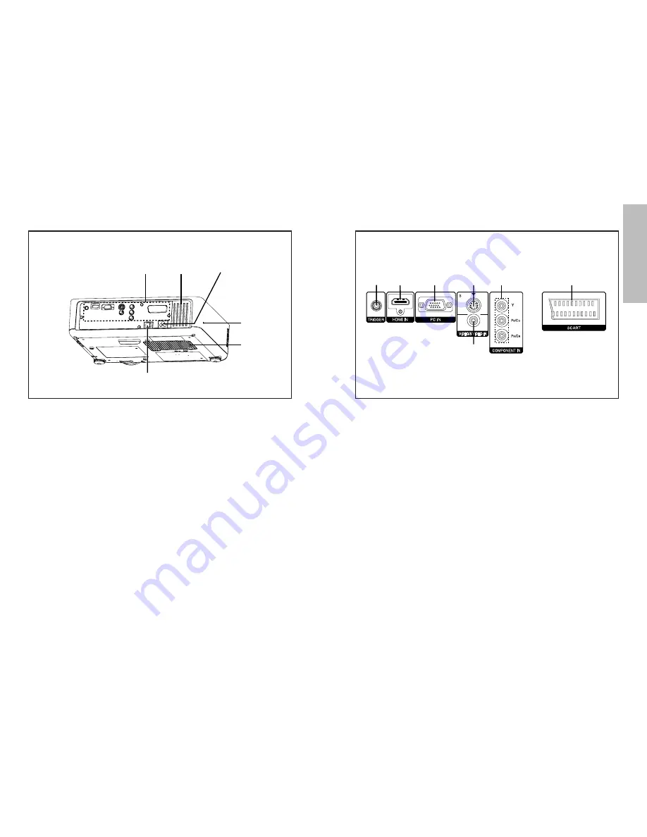
Connector panel

#

$

%

&

'

(

)

#

TRIGGER connector 

(pages 20, 21 and 22)

This connector outputs 12 V when the power is turned on. Connect this
connector to equipment such as an electric screen.

$

HDMI IN connector 

(page 21)

This connector is used to input HDMI signals.

%

PC IN (RGB input) connector 

(page 22)

This connector is used to input RGB signals from a PC.

&

S-VIDEO IN connector 

(page 20)

This connector is used to input signals from an S-VIDEO-compatible
equipment such as a video deck.

'

VIDEO IN connector 

(page 20)

This connector is used to input video signals from a video equipment such
as a video deck.

(

COMPONENT IN [YP

B

P

R

(C

B

C

R

) input] connectors 

(page 20)

These connectors are used to input YP

B

P

R

signals from compatible

equipment such as a DVD player.

)

SCART connector

(page 20)

This connector is used to input SCART signals.

#

Connector panel 

(page 13)

$

Air inlet port

Do not cover this port.

%

Power input socket (AC IN) 

(page 24)

The accessory mains lead is connected here.
Do not use any mains lead other than the accessory mains lead.

&

Security lock 

This can be used to connect a commercially-available theft-prevention
cable (manufactured by Kensington). This security lock is compatible with
the Microsaver Security System from Kensington.

'

Lamp unit cover 

(page 51)

(

MAIN POWER switch 

(pages 24 and 26)

Projector 

<Back and bottom>

#

$

˛

%

(

'

&

Summary of Contents for PT-AE700

Page 1: ...ENGLISH TQBJ 0162 1 LCD Projector Operating Instructions Model No PT AE700E R Before operating this product please read the instructions carefully and save this manual for future use ...

Page 2: ...nce is supplied with a moulded three pin mains plug for your safety and convenience A 13 amp fuse is fitted in this plug Should the fuse need to be replaced please ensure that the replacement fuse has a rating of 13 amps and that it is approved by ASTA or BSI to BS1362 Check for the ASTA mark or the BSI mark on the body of the fuse If the plug contains a removable fuse cover you must ensure that i...

Page 3: ... dimensions calculation methods Dimensions 61 Trademark acknowledgements 62 Precautions with regard to safety WARNING If you notice smoke strange smells or noise coming from the projector disconnect the mains plug from the mains socket BDo not continue to use the projector in such cases otherwise fire or electric shocks could result BCheck that no more smoke is coming out and then contact an Autho...

Page 4: ...a thunderstorm do not touch the projector or the cable BElectric shocks can result Do not use the projector in a bath or shower BFire or electric shocks can result Do not look into the lens while the projector is being used BStrong light is emitted from the projector s lens If you look directly into this light it can hurt and damage your eyes BBe especially careful not to let young children look i...

Page 5: ...jury or contamination of the battery compartment and surrounding area may result Use only the specified batteries BIf incorrect batteries are used they may explode or leak and fire injury or contamination of the battery compartment and surrounding area may result Do not mix old and new batteries BIf the batteries are inserted incorrectly they may explode or leak and fire injury or contamination of...

Page 6: ...e power is frequently turned on and off Liquid crystal panel BDo not project the same image for long periods of time as this may remain as an afterimage on the liquid crystal panel BThe liquid crystal panel of the projector is built with very high precision technology to provide fine picture details Occasionally a few non active pixels may appear on the screen as fixed points of blue green or red ...

Page 7: ...eo signals from a video equipment such as a video deck COMPONENT IN YPBPR CBCR input connectors page 20 These connectors are used to input YPBPR signals from compatible equipment such as a DVD player SCART connector page 20 This connector is used to input SCART signals Connector panel page 13 Air inlet port Do not cover this port Power input socket AC IN page 24 The accessory mains lead is connect...

Page 8: ...s used to display the MAIN MENU When a menu screen is being displayed it can be used to return to a previous screen or to clear the screen INPUT select buttons page 25 These buttons are used to switch the input signals from the connected equipment POWER button pages 24 and 26 LIGHT button page 29 This button is used to illuminate the buttons on the remote control unit KEYSTONE button page 28 This ...

Page 9: ... PKE700 when using the ceiling installation method BIf you set up the projector vertically it may cause damage to the projector BIt is recommended that you set up the projector in a place that is tilted at less than 30 Setting up the projector in places that are tilted at more than 30 may cause malfunctions 16 ENGLISH L SW 82 9 mm 3 1 4 L SH Projector position L Projection distance SH Image height...

Page 10: ...hift lever is moved down full When shift lever is moved up full Screen Screen The values in the table are for the width and the height of the screen NOTE BTurn the shift lever right to secure the shift lever BWhen the lens has been shifted fully to the right or left you will not be able to shift the lens up or down When the lens has been shifted fully up or down you will not be able to shift the l...

Page 11: ...some equipment may not operate correctly for example images may not appear Connections Notes on connections BRead the instruction manual for each peripheral device carefully before connecting it BTurn off the power supply for all peripheral devices before making any connections BIf the cables necessary for connection are not included with the peripheral device or available as an option you may nee...

Page 12: ...e control unit may not operate correctly BIf strong light is allowed to shine onto the remote control signal receptor correct projector operation may not be possible Place the projector as far away from light sources as possible BIf facing the remote control unit toward the screen to operate the projector the operating range of the remote control unit will be limited by the amount of light reflect...

Page 13: ...cator on the projector will flash green After a short period the indicator will illuminate green and a picture will be projected Turn on the power of all connected devices BStart the play function of a device such as a DVD player NOTE BA rattling sound may be heard when the power is turned on and a tinkling sound may be heard when the lamp unit is turned on but these are not signs of malfunctions ...

Page 14: ... indicator on the projector will illuminate orange while the cooling fan is still operating POWER OFF OK CANCEL Press the MAIN POWER switch to turn off the power after the power indicator on the projector illuminates red BDo not cut power to the projector in any way while the cooling fan is still operating Be careful not to switch off the MAIN POWER switch of the projector or unplug the mains lead...

Page 15: ...on BThe buttons on the remote control unit will be illuminated BPress the LIGHT button again to turn off the button lights The button lights will be turned off automatically when no buttons on the remote control unit are pressed for 10 seconds NOTE BThe picture mode can be also selected in the PICTURE menu BWhen the PICTURE MODE menu is selected the settings will switch automatically to the last P...

Page 16: ...is projector allows you to change the aspect ratio to match the type of input signal JUST 4 3 16 9 14 9 ZOOM1 ZOOM2 4 3 16 9 V SCROLL 4 3 16 9 When 525p 480p or 625p 576p signal is being input 4 3 16 9 JUST ZOOM When NTSC 525i 480i or 525p 480p signal is being input AUTO 4 3 16 9 JUST ZOOM S VIDEO VIDEO YPBPR SCART PC HDMI Press the ASPECT button BPressing the ASPECT button will change the aspect ...

Page 17: ...ngement of the COLOUR MNGMT menu BYou can enter the COLOUR MNGMT menu from the ADVANCE MENU in the PICTURE menu page 41 Using COLOR MANAGEMENT You can adjust save and retrieve the settings for the selected colours of the projected image based on the selected picture mode to suit your preference Press the COLOR MANAGEMENT button Press the F or G button to select an item press the I or H button to c...

Page 18: ...nt menu page 33 A will be displayed You can adjust the colour settings again DELETE The selected colour setting will be deleted When all of the settings in the LOG menu are deleted the PROFILE setting will return to NORMAL The confirmation screen will be displayed when the ENTER button is pressed Select OK to delete the settings Press the F or G button to select the setting you want to adjust and ...

Page 19: ... A D J E S C When a YPBPR PC HDMI signal is being input KEYSTONE correction page 28 K E Y S T O N E 0 P O S I T I O N H P O S I T I O N 0 V P O S I T I O N 0 D O T C L O C K 0 C L O C K P H A S E 0 A S P E C T 4 3 A U T O S E T U P S E L E C T E N T E R E S C When a PC signal is being input L A N G U A G E E N G L I S H E N G L I S H D E U T S C H F R A N Ç A I S E S P A Ñ O L I T A L I A N O S E ...

Page 20: ...Unavailable on screen menu items This projector has unadjustable items and unusable functions depending on the signal being input When an item cannot be adjusted or a function cannot be used the corresponding on screen menu display does not appear and the item or function will not work even if the ENTER button is pressed Returning a setting to the factory default If you press the NORMAL button on ...

Page 21: ...button TINT NTSC NTSC 4 43 YPBPR PC HDMI only This adjusts the flesh tones in the picture The flesh tones are greenish I button The flesh tones are reddish H button SHARPNESS To soften the picture details I button To sharpen the picture details H button COLOUR TEMP This is used to adjust the white areas of the picture if they appear bluish or reddish DYNAMIC IRIS ON The amount of light is controll...

Page 22: ...e 58 for details on each type of signal T V S Y S T E M A U T O N T S C N T S C 4 4 3 P A L P A L M P A L N S E C A M NOTE BWhen set to AUTO the projector automatically distinguishes between NTSC NTSC 4 43 PAL PAL60 PAL M PAL N SECAM signals Projecting sRGB compatible pictures sRGB is an international colour reproduction standard IEC61966 2 1 established by the International Electrotechnical Commi...

Page 23: ...llowing procedure ASPECT Refer to page 30 AUTO SETUP PC only H POSITION V POSITION DOT CLOCK and CLOCK PHASE are automatically adjusted according to the input signal Changing the display language Indicates the language which is currently set Select LANGUAGE from the MAIN MENU and then press the ENTER button Press the F or G button to select a language and then press the ENTER button L A N G U A G ...

Page 24: ... N O F F OFF When SCART signals are being input the input select setting and ASPECT will not be set automatically WSS will not be detected from PAL or 625i 576i YPBPR signals FRONT REAR This setting should be changed in accordance with the projector setting up method Refer to page 16 FRONT When the projector is placed in front of a screen REAR When using a translucent screen DESK CEILING This sett...

Page 25: ...ade When the TEMP indicator and the LAMP indicator are illuminated There are two indicators on the control panel of the projector which give information about the operating condition of the projector These indicators illuminate or flash to warn you about problems that have occurred inside the projector so if you notice that one of the indicators is on turn off the power and check the table below f...

Page 26: ...urns Notes on replacing the lamp unit BThe light generating lamp is made of glass so dropping it or allowing it to hit hard objects may cause it to burst Be careful when handling the lamp BDispose of the removed old lamp with the same care that would be taken with a fluorescent light BA Phillips screwdriver is necessary for removing the lamp unit Lamp unit replacement period The lamp is a consumab...

Page 27: ...TE BBe sure to install the lamp unit and the lamp unit cover securely If they are not securely installed it may cause the protection circuit to operate so that the power cannot be turned on Lamp unit replacement procedure Turn off the MAIN POWER switch according to the procedure given in Turning off the power on page 26 and then disconnect the mains plug from the mains socket and check that the ar...

Page 28: ...points Problem Possible cause Page Power does not turn on No picture appears The picture is fuzzy The colour is pale or grayish The remote control unit does not operate The picture does not display correctly BThe mains lead may not be connected BThe MAIN POWER switch is turned off BThe main power supply is not being supplied to the mains socket BTEMP indicator is illuminated or flashing BLAMP indi...

Page 29: ...ngle line D sub HD 15 pin female R G B 0 7 V p p 75 Ω G SYNC 1 0 V p p 75 Ω HD SYNC TTL high impedance automatic positive negative polarity compatible VD TTL high impedance automatic positive negative polarity compatible COMPONENT IN Y PB CB PR CR Single line RCA pin jack x 3 Y 1 0 V p p Including sync 75 Ω PB PR CB CR 0 7 V p p 75 Ω HDMI IN Single line 19 pin HDMI connector SCART in Single line 2...

Page 30: ... 67 5 74 9 108 0 A PC 1 280 x 1 024 64 0 60 0 108 0 A PC 1 360 x 768 48 8 59 8 73 8 A PC Display resolution dots 1 Scanning frequency H kHz V Hz Dot clock frequency MHz Picture quality 2 NTSC NTSC4 43 PAL M PAL60 PAL PAL N SECAM 525i 480i 625i 576i 525p 480p 625p 576p 1 125 1 080 60i 1 125 1 080 50i 750 720 60p 750 720 50p VGA480 WIDE480 SVGA WIDE600 WIDE720 XGA WIDE768 MXGA SXGA WIDE768 2 Format ...

Page 31: ...culation methods Dimensions such as projection distances can be calculated from the screen diagonal length Units for calculations m SD SW 16 9 SH LW LT Screen Width SW SDx0 872 Screen Height SH SDx0 490 Minimum Projection Distance LW 1 2244xSD 0 056 Maximum Projection Distance LT 2 4449xSD 0 056 The values obtained from the formulas above are approximate ...

Page 32: ...ions are printed on recycled paper Trademark acknowledgements BVGA and XGA are trademarks of International Business Machines Corporation BS VGA is a registered trademark of the Video Electronics Standards Association BHDMI the HDMI logo and High Definition Multimedia Interface are trademarks or registered trademarks of HDMI Licensing LLC All other trademarks are the property of the various tradema...

Reviews: