background image

Appendix

Technical Information

E

NGLISH - 58

J

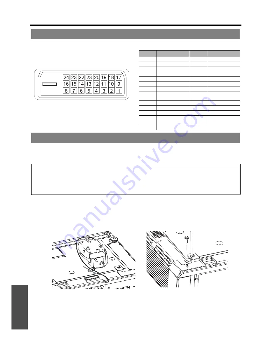
Pin assignments and signal names

The projector and the ceiling mount bracket are designed sufficiently safety though, make sure the safety cable 
provided with the projector is installed and attached to the bottom of the projector when mounting on the ceiling for 
safety and security.

J

Installing the safety cable

1. Install the ceiling mount bracket according to the installation instructions.
2. Loop the security cable around the ceiling mount bracket with less slack.


Lace the cable of the end with a latch through the loop on the other end of the cable.

3. Attach the latch on to the bottom of the projector with a provided screw.


Torque: 1.25±0.2 N·m

* Indicated sample above is ET-PKF100S.

DVI-D IN terminal

Pin No.

Signal name

Pin No.

Signal name

1

TMDS  Data  2-

13

2

TMDS  Data  2+

14

+5V

3

TMDS Data 2/4 
shield

15

GND

4

16

Hot Plug Detect

5

17

TMDS Data 0-

6

DDC clock

18

TMDS Data 0+

7

DDC data

19

TMDS Data 0/5 
shield

8

20

9

TMDS  Data  1-

21

10

TMDS Data 1+

22

TMDS clock shield

11

TMDS Data 1/3 
shield

23

TMDS clock+

12

24

TMDS clock-

Ceiling mount bracket safeguards

NOTE:

• Even if it is guarantee period, the manufacturer is not responsible for any hazard or damage caused by using a ceiling 

mount bracket which is not purchased from an authorised distributors, or environmental conditions.

• Make sure to use a torque driver and do not use an electrical screwdriver or an impact screwdriver.
• Installation work of the ceiling mount bracket should only be carried by a qualified technician.
• Remove an unused ceiling mount bracket promptly.

Summary of Contents for PT-FW300E

Page 1: ...Operating Instructions LCD Projector Model No PT FW300NTE PT FW300E Before operating this product please read the instructions carefully and save this manual for future use TQBJ0284 2 Commercial Use PT FW300NTE ...

Page 2: ...ged period of time 2 To prevent electric shock do not remove cover No user serviceable parts inside Refer servicing to qualified service personnel 3 Do not remove the earthing pin on the mains plug This apparatus is equipped with a three prong earthing type mains plug This plug will only fit an earthing type mains socket This is a safety feature If you are unable to insert the plug into the mains ...

Page 3: ...appropriate waste handling For more information about collection and recycling of old products and batteries please contact your local municipality your waste disposal service or the point of sale where you purchased the items Penalties may be applicable for incorrect disposal of this waste in accordance with national legislation For business users in the European Union If you wish to discard elec...

Page 4: ...bH Panasonic Testing Centre Winsbergring 15 22525 Hamburg F R Germany Ce produit est conçu pour l utilisation dans les pays suivants Autriche Belgique Bulgarie République Tchéquie Chypre Danemark Estonie Finlande France Allemagne Grèce Hongrie Islande Irlande Italie Lettonie Lituanie Luxembourg Malte Pays Bas Norvège Pologne Portugal Roumanie Slovénie Slovaquie Espagne Suède Suisse et Royaume Uni ...

Page 5: ...Important Safety Notice ENGLISH 5 Important Information ...

Page 6: ...nput signal 26 Positioning the image 26 Remote control operation 27 Operating range 27 Setting up the image position automatically 27 Switching the input signal 28 Enlarging the centred area 28 Capturing an image 29 Stopping the projection 29 Resetting to the factory default settings 29 Projecting an image in INDEX WINDOW mode 29 Using an assigned function 30 Projecting 2 different source image at...

Page 7: ...OMPUTER2 SELECT 43 NO SIGNAL SHUT OFF 43 INITIAL START UP 43 INSTALLATION 44 HIGH ALTITUDE MODE 44 EMULATE 44 FUNCTION BUTTON 44 AUDIO SETTING 44 TEST PATTERN 45 INITIALIZE ALL 45 FILTER COUNTER RESET 45 SECURITY menu 46 PASSWORD 46 PASSWORD CHANGE 46 TEXT DISPLAY 46 TEXT CHANGE 46 MENU LOCK 47 MENU LOCK PASSWORD 47 CONTROL DEVICE SETUP 47 NETWORK menu 48 Items in NETWORK menu 48 TEMP LAMP and FIL...

Page 8: ...ket and wipe it with a dry cloth If not using the projector for an extended period of time pull the mains plug out from the mains socket Do not handle the mains plug with wet hands Failure to observe this may result in electric shocks Insert the mains plug securely into the mains socket Do not use other than the provided mains lead If the plug is not inserted correctly electric shocks or overheati...

Page 9: ...e burns Before replacing the lamp be sure to disconnect the mains plug from the mains socket Electric shocks or explosions can result if this is not done Do not allow infants or pets to touch the remote control unit Keep the remote control unit out of the reach of infants and pets after using it Do not cover the air inlet port or the air outlet port Doing so may cause the projector to overheat whi...

Page 10: ...he broken pieces Failure to observe this may cause the user to absorb the gas which was released when the lamp broke and which contains nearly the same amount of mercury as fluorescent lamps and the broken pieces may cause injury If you believe that you have absorbed the gas or that the gas has got into your eyes or mouth seek medical advice immediately Ask your dealer about the replacement of the...

Page 11: ...igh precision technology to provide fine picture details Occasionally a few stuck pixels may appear on the screen as fixed points of blue green or red It is recommended to switch off the projector once and try after 1 hour later again Please note that this does not affect the performance of your LCD The projector has a high pressure mercury lamp and that is characterised as follows The brightness ...

Page 12: ...g cover or foam cartons must be treated properly Contact to an Authorised Service Centre for lost accessories Accessories Remote control for PT FW300NTE x1 N2QAYB000305 Remote control for PT FW300E x1 N2QAYB000367 AA batteries for remote control x2 Safety cable TTRA0141 Attachment screw x1 Safety cable x1 Mains lead x1 K2CM3DH00016 CD ROM x1 TQBH9012 Power cord secure lock x1 TTRA0183 ...

Page 13: ...f the screen HIGH Displays the menu in the upper part of the screen HIGH ALTITUDE MODE If you use the projector at high elevation the HIGH ALTITUDE MODE setting need to be ON to set the fan speed high OFF The fan speed is low ON The fan speed is high Minimum required setting screen INITIAL SETTING ENGLISH SELECT ENTER PLEASE SELECT LANGUAGE INSTALLATION INITIAL SETTING FRONT DESK HIGH ALTITUDE MOD...

Page 14: ...ever page 19 Projection lens Front panel cover Hold both sides of the top corner of the front panel cover to open or close While not operating the controls panel keep the front panel cover closed Remote control signal receptor page 27 Power button While the main power is on switch between stand by mode and projection mode page 25 INPUT SELECT button Switch to cycle through the input method page 26...

Page 15: ... of this opening Burglar hook port Attach a commercial burglar prevention cable AC IN Connect the mains lead to supply electronic power to the projector page 23 VARIABLE AUDIO OUT Connect an audio cable for outputting audio signals to the connected equipment COMPUTER AUDIO IN Connect audio cables for inputting audio signals corresponding to COMPUTER1 IN COMPUTER2 IN 1 OUT and or DVI D IN terminals...

Page 16: ...tcut page 30 Control to change the scale by means of digital zoom page 28 Automatically adjust the setting of SHIFT DOT CLOCK CLOCK PHASE and SIGNAL SEARCH for the projected image of COMPUTER DVI signal page 27 Switch the required input signal button to select Return to the previous menu page 34 Turn off the projection temporarily page 29 Display the frozen image while the display of subsequent im...

Page 17: ...5 7 2 3 m 7 6 4 6 m 15 1 2 29 m 90 1 21 m 3 11 1 94 m 6 4 2 6 m 8 6 5 1 m 16 8 2 54 m 100 1 35 m 4 5 2 15 m 7 2 9 m 9 6 5 7 m 18 8 3 05 m 120 1 62 m 5 3 2 58 m 8 5 3 4 m 11 1 6 9 m 22 7 3 81 m 150 2 02 m 6 7 3 23 m 10 7 4 3 m 14 1 8 6 m 28 2 5 08 m 200 2 69 m 8 9 4 31 m 14 1 5 7 m 18 8 11 5 m 37 8 6 35 m 250 3 37 m 11 5 38 m 17 7 7 2 m 23 7 14 3 m 46 10 7 62 m 300 4 04 m 13 3 6 46 m 21 2 8 6 m 28 ...

Page 18: ...N FRONT DESK INSTALLATION REAR DESK J Mounting on the ceiling and projecting from front J Mounting on the ceiling and projecting from rear INSTALLATION FRONT CEILING INSTALLATION REAR CEILING NOTE A translucent screen is required for rear projection When mounting the projector on the ceiling the optional ceiling mount bracket ET PKF100H ET PKF100S is required See Ceiling mount bracket safeguards o...

Page 19: ...lace the projector where the projector lens is up to 24 horizontally off centre from the screen and then adjust the image position with the lens shift lever Q Vertical shift You can place the projector where the projector lens is up to 51 vertically off centre from the screen and the adjust the image position with the lens shift lever Lens shift and positioning Shifting the lever right Image moves...

Page 20: ... will get the best quality of the projection image When the lens shift lever is at the vertical limit of the shift range you cannot move the lever to the horizontal limit likewise when the lens shift lever is at the horizontal limit of the shift range you cannot move the lever to the vertical limit When the projector is tilted and you adjust KEYSTONE the centre of the screen and the lens need to b...

Page 21: ...ojector Connecting example Computers NOTE Use COMPUTER terminals to input YPBPR signals When connecting to the COMPUTER terminals you can switch the audio input terminal between COMPUTER AUDIO IN and AUDIO IN See AUDIO SETTING on page 44 When COMPUTER2 SELECT in the OPTION menu is set to OUTPUT do not connect any input signals See CD ROM contents for the LAN network connection NOTE Do not touch th...

Page 22: ...g of the DVI EDID in DISPLAY OPTION menu with some DVI D IN connection See DVI D IN on page 40 Malfunction may occur or other problems could be encountered with some kind of HDMI or DVI equipment When connecting to the DVI D IN terminal you can switch the audio input terminal between COMPUTER AUDIO IN 2 and AUDIO IN See AUDIO SETTING on page 44 DVD player Audio system To S VIDEO output Video playe...

Page 23: ... by internal power supply J Direct power on function You can start the projection with only supplying the electric power See INITIAL START UP on page 43 J Direct power off function You can switch off the electric power supply any time by unplugging the mains plug from the mains socket or by switching off the main power The internal lamp cooling fan keeps operating by the internal power supply and ...

Page 24: ... NETWORK STANDBY in NETWORK menu or IN STANDBY MODE of AUDIO SETTING in PROJECTOR SETUP menu is set to ON Press the power button to start the projection GREEN Flashing The power is switched on and the projector is getting ready to project Lit Projecting ORANGE Lit The power is switched off and the projector is cooling the lamp The indicator will light or flash and start the projection after a shor...

Page 25: ...orange while cooling the lamp then illuminates red when is ready to switch off the MAIN POWER 4 Switch off the MAIN POWER on the back of the projector Switching on the projector NOTE When starting up the projector some small rattling or tinkling sound may be heard or the display may flicker for the characteristics of the lamp Those are normal and will not affect the performance of the projector Wh...

Page 26: ...gle vertically See Front leg adjusters and throwing angle on page 18 4 Adjust the focus and the projected image size Turn the focus lever and zoom lever to adjust the image You can confirm the adjusted effect with the TEST PATTERN in OPTION menu See TEST PATTERN on page 45 Selecting the input signal NOTE SIGNAL SEARCH is ON as default and the signal from the connected devices is detected automatic...

Page 27: ...T CLOCK and CLOCK PHASE in the POSITION menu automatically for the projected COMPUTER signal image With DVI signal adjust SHIFT setting only Operating range Shown as PT FW300NTE NOTE Do not let strong light shine onto the signal receptor The remote control may malfunction under strong light such as fluorescent If there are any obstacles between the remote control and the remote control signal rece...

Page 28: ... 1 Press the DIGITAL ZOOM button once The centred area of the image will then be enlarged to 1 5x 2 Adjust the image size by pressing the DIGITAL ZOOM button The image size will be changed in steps of 0 1 Q Shifting the centre point Press F G I H to shift the centre point Switching the input signal NOTE If you select an unplugged input method the guidance will blink on and off several times See Li...

Page 29: ...default the frozen image is displayed on the left and the subsequent image is displayed on the right Press I H to switch the position Q Changing the image size Press F G to capture a new image and change the size in 2 ways Q Capturing a new image While in INDEX WINDOW mode press the ENTER button to capture a new image and the frozen image window will be updated in a while Capturing an image Stoppi...

Page 30: ...ge 44 Projecting 2 different source image at a time COMPUTER1 IH COMPUTER2 FG FG DVI S VIDEO FG FG NETWORK IH VIDEO Image 1 Image 1 Image 2 Image 1 COMPUTER1 COMPUTER2 VIDEO IN S VIDEO IN DVI D NETWORK connection Still Movie Still Movie Still Movie COMPUTER1 Still N A N A OK OK OK OK OK OK OK Movie N A N A OK N A N A N A OK N A OK COMPUTER2 Still OK OK N A N A OK OK OK OK OK Movie OK N A N A N A N...

Page 31: ...g the laser pointer NOTE If you press the disabled LASER button the alert LASER POINTER IS DISABLED will be displayed on the screen While the menu is displaying the alert will not be displayed CAUTION Use of controls of adjustments or performance of procedures other than those specified herein may result in hazardous radiation exposure On Off Deactivating switch Top view Laser pointer beam emitter...

Page 32: ... 35 Default 0 1 Available with still image of COMPUTER DVI signals only WHITE BALANCE GREEN 1 page 35 Default 0 WHITE BALANCE BLUE 1 page 35 Default 0 COLOR TEMPERATURE page 36 DEFAULT LOW HIGH DAYLIGHT VIEW page 36 AUTO OFF ON DIGITAL CINEMA REALITY page 36 ON OFF NOISE REDUCTION page 36 OFF ON TV SYSTEM page 36 AUTO NTSC NTSC 4 43 PAL PAL M PAL N SECAM RGB YPBPR page 36 AUTO RGB YPBPR KEYSTONE p...

Page 33: ...BY INSTALLATION page 44 FRONT DESK FRONT CEILING REAR DESK REAR CEILING HIGH ALTITUDE MODE page 44 OFF ON EMULATE page 44 DEFAULT D3500 D4000 D W5K series L730 L780 L735 L785 LB W80 FUNCTION BUTTON page 44 DISABLE ASPECT PICTURE MODE DAYLIGHT VIEW AUDIO SETTING page 44 VOLUME Default 20 BALANCE Default 0 IN STANDBY MODE OFF ON AUDIO IN SELECT DVI COM AUDIO IN 2 AUDIO IN COMPUTER1 COM AUDIO IN 1 AU...

Page 34: ... level the next level will be displayed 3 Press I H to adjust or set the selected item For items using a bar scale the current settings are displayed on the left of the bar scale You can cycle through the options of an item by pressing I H 4 Press the MENU or RETURN button to return to the previous menu Navigating through the menu PICTURE POSITION PICTURE MODE CONTRAST BRIGHTNESS COLOR TINT SHARPN...

Page 35: ...ly You can adjust the white balance more properly in green colour temperature by pressing I H Available with RGB DVI still signals only You can adjust the white balance more properly in blue colour temperature by pressing I H Available with RGB DVI still signals only PICTURE MODE STANDARD Setting for a general image DYNAMIC Bright and sharp setting BLACKBOARD Setting for when projecting on a black...

Page 36: ...the options Available with S VIDEO VIDEO only The projector will detect the signal from the COMPUTER terminals if the signal is RGB or YPBPR You can turn off the automatic detecting system and switch between RGB and YPBPR manually AUTO Automatic detecting system RGB Project as RGB signal YPBPR Project as YPBPR signal COLOR TEMPERATURE DAYLIGHT VIEW NOTE Do not cover the Ambient Luminance Sensor AL...

Page 37: ...with signals of RGB DVI still only If the 4 edges of an image is partly dropped you can use this function to adjust and project it properly Not available with signals of NETWORK I Shrink H Enlarge KEYSTONE Image Operation NOTE You can correct the distortion 30 degrees from the plane For a better quality image installing the projector with a minimum of distortion is recommended Some distortion may ...

Page 38: ...tected the image will be projected without any change and other signals will be adjusted to 16 9 Q H FIT The 4 3 5 4 image will be stretched to the horizontal limit of the SCREEN FORMAT setting size with preserving original ratio and the vertical edge will be cropped Q V FIT The 16 9 16 10 15 9 image will be stretched to the vertical limit of the SCREEN FORMAT setting size with preserving original...

Page 39: ...IH HV FIT IH THROUGH 4 3 IH H FIT IH HV FIT COMPUTER WXGA768 WIDE720 1 080 60p 1 080 50p 16 9 IH V FIT IH HV FIT IH 4 3 4 3 IH HV FIT WIDE signals except WXGA768 WIDE720 1 080 60p 1 080 50p 16 9 IH 4 3 4 3 IH HV FIT NOTE If you project an image with an unmatched aspect ratio the image may distort or some portions may be cropped Select an aspect ratio which preserves the intention of the image crea...

Page 40: ...osition of the menu When SCREEN FORMAT is set to 16 10 you can change the displaying position of the menu Press I H to select the required option LOW Displays the menu in the lower part of the screen CENTER Displays the menu in the middle of the screen HIGH Displays the menu in the upper part of the screen ON SCREEN DISPLAY Options Function DETAILED Display the input method by graphic The INPUT GU...

Page 41: ...G and edit the TEXT2 if you need to and repeat the step 3 You can turn off the AUTO SETUP button function for when the COMPUTER signal is detected AUTO When the projector detects a COMPUTER or DVI signal adjust the projected image position automatically for SHIFT SIGNAL SEARCH DOT CLOCK and CLOCK PHASE BUTTON Only when the AUTO SETUP button is pressed the projected image position will be adjusted ...

Page 42: ...te control OTHER FUNCTIONS Menu items Refer AUTO SETUP See page 27 FREEZE See page 29 AV MUTE See page 29 SIDE BY SIDE See page 30 INDEX WINDOW See page 29 DIGITAL ZOOM You can enlarge the projected image Press I H to adjust the size and press the ENTER button Press the RETURN button to return to the normal projection ...

Page 43: ...s lead is connected STATUS Items Description Q SIGNAL NAME Projecting signal name FREQUENCY Projecting signal frequency Q RUNTIME PROJECTOR Duration of projector used time LAMP Duration of lamp used time Q REMAINING FILTER QUANTITY Quantity of filter remaining Remote control Control panel See Navigating through the menu on page 34 See Main menu and Sub menu on page 32 COMPUTER2 SELECT NO SIGNAL SH...

Page 44: ...dio in standby mode J AUDIO IN SELECT You can switch the audio output method for COMPUTER1 IN COMPUTER2 IN and DVI D IN terminals Q DVI COM AUDIO IN 2 Output audio that is input to the COMPUTER AUDIO 2 AUDIO IN Output audio that is input to the AUDIO IN Q COMPUTER1 COM AUDIO IN 1 Output audio that is input to the COMPUTER AUDIO 1 AUDIO IN Output audio that is input to the AUDIO IN INSTALLATION FRO...

Page 45: ...er by pressing the power button 4 Switch off the MAIN POWER button to reset the projector 5 Switch on the MAIN POWER button 6 Press the power button 7 The minimum required setting screen will be displayed See Minimum required setting screen on page 13 After you replaced the Auto Cleaning Filter ACF REMAINING FILTER of STATUS in PROJECTOR SETUP need to be reset to 0 1 Press the ENTER button for mor...

Page 46: ...o 22 characters for TEXT DISPLAY 1 Enter your original text Use F G I H to specify the location of the required character Move the cursor to ALL DELETE and press the ENTER button to delete all the entered text line Press the DEFAULT button to delete the last entered character or indicated with the cursor in the text line To insert a character in the entered text line move the cursor to the text bo...

Page 47: ...buttons The confirmation screen will be displayed Select OK by pressing the I and the ENTER button J REMOTE CONTROLLER You can disable the remote control buttons Press I or H to switch the option ENABLE Enable the remote control buttons DISABLE Disable the remote control buttons The confirmation screen will be displayed Select OK by pressing the I and the ENTER button MENU LOCK NOTE The factory de...

Page 48: ...ER SEARCH MULTI LIVE STATUS INITIALIZE NOTE See more detailed instructions in the contents of the CD ROM which is provided with the projector Remote control Control panel See Navigating through the menu on page 34 See Main menu and Sub menu on page 32 Items in NETWORK menu NOTE When you activated the security system in SECURITY menu you need to perform the security password operation to initialise...

Page 49: ...maged Remedy See Replacing the Lamp unit on page 50 Let the lamp unit cool down and turn on the MAIN POWER after 90 seconds Contact an Authorised Service Centre See Replacing the Lamp unit on page 50 Indicator Illuminating red while projecting and the alert will be displayed Flashing red and power is turned off Problem The temperature inside and or outside the projector is abnormally high Cause Th...

Page 50: ...ly under the projector or put your face closer to the projector J When to replace the lamp unit The lamp unit is consumable and the brightness decreases by duration of usage The LAMP indicator will inform you of the replacement timing at 5 000 hours and at 6 000 hours the projector will be turned off Those figures are rough guidance and might be shortened by the usage conditions characteristics of...

Page 51: ...cket Prepare a Phillips head screwdriver Contact an Authorised Service Centre to purchase a replacement ACF ET ACF100 J When to replace the ACF ACF is consumable product and effects on ventilation The FILTER indicator will inform you of the replacement timing You can check the remaining amount of the ACF in REMAINING FILTER of STATUS in PROJECTOR SETUP menu Lamp unit cover fixing screws Lamp unit ...

Page 52: ...th a Phillips head screwdriver J Resetting the REMAINING FILTER 1 Turn on the projector and display the FILTER COUNTER RESET in PROJECTOR SETUP 2 Press the ENTER button for more than 3 seconds The confirmation screen will be displayed 3 Select OK by pressing I then press the ENTER button 4 Display the STATUS and confirm the figure NOTE If the ACF and or ACF cover are attached incorrectly the proje...

Page 53: ...VICE SETUP in SECURITY menu is disabled If you have a loss of the remote control while the CONTROL PANEL is disabled press and hold the MENU button for 2 seconds with pressing the ENTER button 47 The remote control does not operate REMOTE CONTROLLER of CONTROL DEVICE SETUP in SECURITY menu is disabled The batteries may be weak The batteries may not have been inserted correctly The remote control s...

Page 54: ... 280 x 720 37 5 50 0 74 3 AA D VESA 640 x 400 31 5 70 1 25 2 A C 640 x 400 37 9 85 1 31 5 A VGA 640 x 480 31 5 59 9 25 2 A D D D C 640 x 480 35 0 66 7 30 2 A D C 640 x 480 37 9 72 8 31 5 A D 640 x 480 37 5 75 0 31 5 A D 640 x 480 43 3 85 0 36 0 A SVGA 800 x 600 35 2 56 3 36 0 A D 800 x 600 37 9 60 3 40 0 A D D D C 800 x 600 48 1 72 2 50 0 A D C 800 x 600 46 9 75 0 49 5 A D 800 x 600 53 7 85 1 56 3...

Page 55: ...ext command When a command which does not require parameters to be sent the colon is not required If an incorrect command is sent from the personal computer the ER401 command will be sent from the projector to the personal computer Serial terminal Pin No Signal name Contents A NC B TXD Transmitted data C RXD Received data D NC E GND Earth F NC G RTS Connected internally H CTS I NC Signal level RS ...

Page 56: ...r the lamp has switched off the lamp is not turned back on again straight away in order to protect the lamp AVL Volume Parameter 000 063 Adjustment value 0 63 IIS INPUT Parameter VID VIDEO RG1 COMPUTER1 DVI DVI SVD S VIDEO RG2 COMPUTER2 NWP NETWORK Q S Lamp condition query Call back 0 Standby 1 Lamp ON control active 2 Lamp ON 3 Lamp OFF control active OSH AV MUTE Turning off the projection and so...

Page 57: ...ontrol by external contact Pin No Settings B A Short Open Operation On Off Pin No Settings C A Open Open Open Short Short Open E A Open Short Open Open Short Short F A Open Open Short Open Open Short Input signal COMPUTER1 COMPUTER2 DVI VIDEO S VIDEO NETWORK NOTE When pin A and pin I are short circulated the buttons on the projector s control panel power and INPUT SELECT buttons on the remote cont...

Page 58: ... 25 0 2 N m Indicated sample above is ET PKF100S DVI D IN terminal Pin No Signal name Pin No Signal name 1 TMDS Data 2 13 2 TMDS Data 2 14 5V 3 TMDS Data 2 4 shield 15 GND 4 16 Hot Plug Detect 5 17 TMDS Data 0 6 DDC clock 18 TMDS Data 0 7 DDC data 19 TMDS Data 0 5 shield 8 20 9 TMDS Data 1 21 10 TMDS Data 1 22 TMDS clock shield 11 TMDS Data 1 3 shield 23 TMDS clock 12 24 TMDS clock Ceiling mount b...

Page 59: ...8 6 5 3 m 17 4 100 2 54 m 1 25 m 4 1 2 21 m 7 3 2 9 m 9 6 5 9 m 19 4 120 3 05 m 1 49 m 4 10 2 66 m 8 8 3 5 m 11 5 7 1 m 23 3 150 3 81 m 1 87 m 6 1 3 32 m 10 10 4 4 m 14 5 8 8 m 28 10 200 5 08 m 2 49 m 8 2 4 43 m 14 6 5 9 m 19 4 11 8 m 38 8 250 6 35 m 3 11 m 10 2 5 53 m 18 1 7 4 m 24 3 14 7 m 48 2 300 7 62 m 3 74 m 12 3 6 64 m 21 9 8 9 m 29 2 17 7 m 58 Screen size and throw distance for 4 3 aspect ...

Page 60: ...ion all comply with ISO21118 international standards 3 500 lm Operating environment Temperature 0 C 40 C 32 F 104 F When the HIGH ALTITUDE MODE page 44 is set to ON 0 C 35 C 32 F 95 F Humidity 20 80 no condensation Scanning frequency 3 for RGB signal 3 See List of compatible signals on page 54 for available signals Horizontal scanning frequency 15 kHz 91 kHz Vertical scanning frequency 50 Hz 85 Hz...

Page 61: ...eo compatible 0 V rms 2 0 V rms variable SERIAL D sub 9 pin RS 232C compatible REMOTE D sub 9 pin For external control LAN RJ 45 Single line For network connection 10 Base T 100Base TX Wireless LAN PT FW300NTE only Compatible IEEE802 11b IEEE802 11g Wireless LAN standard protocol Wireless channel IEEE802 11b IEEE802 11g 1 13 channels Distance 30 m 98 5 Depends on the usage environment Cabinet Moul...

Page 62: ...o and High Definition Multimedia Interface are trademarks or registered trademarks of HDMI Licensing LLC The font used in the on screen displays is a Ricoh bitmap font which is manufactured and sold by Ricoh Company Ltd All other trademarks are the property of the various trademark owners Dimensions Trademark acknowledgements 323 12 11 16 64 5 2 17 32 9 5 11 32 432 17 85 4 3 11 32 53 2 1 16 128 5 ...

Page 63: ...utton 16 Remote control function 28 Dimensions 62 Direct power off 23 Direct power on 23 DISPLAY OPTION menu 40 DOT CLOCK 37 DOUBLE WINDOW 30 DVI EDID 40 DVI SIGNAL LEVEL 40 DVI D IN 15 40 Pin assignments 58 E EMULATE 44 ENTER Control panel button 14 Remote control button 16 F FILTER COUNTER RESET 45 Focus lever 14 26 FRAME LOCK 39 FREEZE Remote control button 16 Remote control function 29 Front l...

Page 64: ... YPBPR 36 RUNTIME 43 S Safety cable Accessories 12 Safeguards 58 SCREEN FORMAT 40 SCREEN POSITION 40 SCREEN SETTING 40 Screen size 16 10 17 16 9 59 4 3 59 Security lock 15 SECURITY menu 46 SERIAL 15 Basic format 55 Cable specifications 56 Communication settings 55 Connection 55 Control commands 56 Pin assignments 55 SHARPNESS 35 SHIFT 37 SHIFT V 37 SIDE BY SIDE Remote control button 16 Remote cont...

Page 65: ......

Page 66: ...Printed in Japan S0908 3019D ...

Reviews: