22
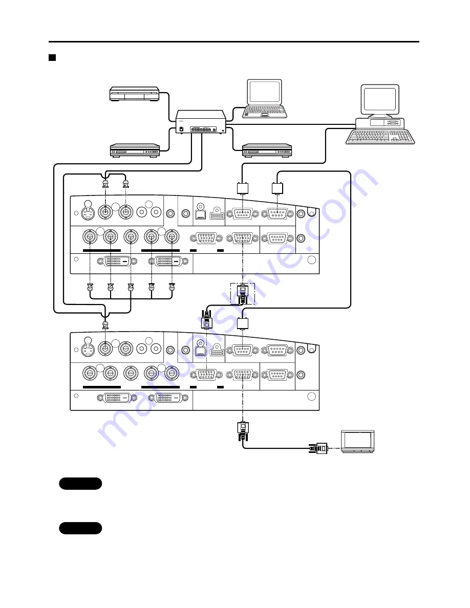
Example of connecting with system switcher
Setting-up
REMOTE
RGB OUT
OUT
WIRED
IN
IN
OUT
IN
R/R-Y/P
R
G/Y
SYNC/HD
VD
B/B-Y/P
B
IN
OUT
OUT
IN
R
L
USB
SERIAL
S-VIDEO IN
AUDIO IN
RGB
AUDIO AUDIO
VIDEO
RGB 2 IN
OUT
IN
DVI-D
RGB 1 IN
> PC <
TBMU152
OUT
REMOTE
RGB OUT
OUT
WIRED
IN
IN
OUT
IN
R/R-Y/P
R
G/Y
SYNC/HD
VD
B/B-Y/P
B
IN
OUT
OUT
IN
R
L
USB
SERIAL
S-VIDEO IN
AUDIO IN
RGB
AUDIO AUDIO
VIDEO
RGB 2 IN
OUT
IN
DVI-D
RGB 1 IN
> PC <
TBMU152
OUT
OFF
OFF
POWER
ON
INPUT SELECT
1
2
3
4
5
6
VP
ON/OFF
Signal Selector TW-SWS J
Note PC
Control PC
Colour monitor with
RGB video ports
Digital STB
DVD player
System switcher
Video deck
* 1
Note
• Read the operating instructions for the system switcher carefully.
Caution
• *1 An asterisk denotes that the second projector requires positioning if the RGB outputs are connected in a
daisy chain. However, the signals should be divided at the signal source if possible.


