ENGLISH - 23
Attention
f
When a LAN cable is directly connected to the projector, the network connection must be made indoors.
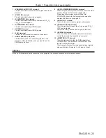
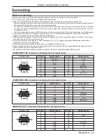
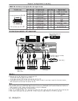
1 <VARIABLE AUDIO OUT> terminal
This is the terminal to output the audio signal input to the
projector.
2 <VIDEO IN> terminal
This is the terminal to input video signals.
3 <COMPUTER 1 IN> terminal
This is the terminal to input RGB, Component (YC
B
C
R
/
YP
B
P
R
) or S-video signals.
4 <COMPUTER 2 IN> terminal
This is the terminal to input RGB signals.
5 <HDMI IN> terminal
This is the terminal to input HDMI signals.
6 <LAN> terminal
This is the LAN terminal to connect to the network.
7 <USB B (DISPLAY)> terminal
This terminal is used to connect the projector to the
computer with a USB cable when you want to use the
USB Display function.
8 <USB A (VIEWER/WIRELESS)> terminal
When using the Memory Viewer function, insert the USB
memory directly to this terminal. (
x
page 76 )
Please insert the wireless module (Model No.:
ET-WML100) directly to this terminal when using the
wireless LAN function. (
x
page 82 )
9 <AUDIO IN 1> terminal
This is the terminal to input computer audio signals.
10 <AUDIO IN 2 (L/R)> terminal
This is the terminal to input Video, S-video and YC
B
C
R
/
YP
B
P
R
audio signals.
There are a left (L) terminal and a right (R) terminal.
11 <SERIAL IN> terminal
This is the RS-232C compatible terminal to externally
control the projector by connecting a computer.
12 <MONITOR OUT> terminal
This is the terminal to output the RGB signals from
<COMPUTER 1 IN> terminal or <COMPUTER 2 IN>
terminal to external monitor.
This terminal will output the corresponding input signals
when switching to Computer 1 or Computer 2 input.
Chapter 1 Preparation - About your projector

