Chapter 4
Settings — [NETWORK] menu
ENGLISH - 187
4) Press the <ENTER> button.
f
The
[DIGITAL LINK STATUS]
screen is displayed.
[LINK STATUS]
The content of display is as follows.
[DIGITAL LINK]: Communicating in the DIGITAL LINK method.
[LONG REACH]: Communicating in the long reach method.
[ETHERNET]: Communicating in the Ethernet method.
[NO LINK]: Communication is not established.
[HDCP STATUS]
The content of display is as follows.
[HDCP2.2]: When protected with HDCP 2.2
[HDCP1.X]: When protected with HDCP 1.X
[NONE]: When not protected with HDCP
[―]: When there is no signal
[SIGNAL QUALITY]
[SIGNAL QUALITY] is a numerical value of the amount of error, and the display color changes to
green, yellow, or red depending on that value.
Check the signal quality level while receiving a signal from the twisted-pair-cable transmitter.
f
[MAX]/[MIN]: Maximum/minimum value of the amount of error
f
Green (
-12 dB or lower)
→
normal signal quality level.
f
Yellow (
-11 to -8 dB)
→
caution level that noise may appear on the screen.
f
Red (
-7 dB or higher)
→
abnormal level with interrupted synchronization and receiving not
possible.
[DIGITAL LINK MENU]
When the optional DIGITAL LINK output supported device (Model No.: ET‑YFB100G, ET‑YFB200G) is connected
to the <DIGITAL LINK/LAN> terminal, the main menu of the connected DIGITAL LINK output supported device is
displayed. Refer to the Operating Instructions of the DIGITAL LINK output supported device for details.
Note
f
[DIGITAL LINK MENU] cannot be selected when [EXTRON XTP] is set to [ON].
f
The operation guidance for the “RETURN” button is in the menu screen of the Digital Interface Box and DIGITAL LINK Switcher. The
projector does not have the “RETURN” button, but the same operation is available with the <MENU> button.
[EXTRON XTP]
Perform the connection setting for the “XTP transmitter” of Extron Electronics.
1) Press
as
to select [DIGITAL LINK].
2) Press the <ENTER> button.
f
The
[DIGITAL LINK]
screen is displayed.
3) Press
as
to select [EXTRON XTP].
4) Press
qw
to switch the item.
f
The items will switch each time you press the button.
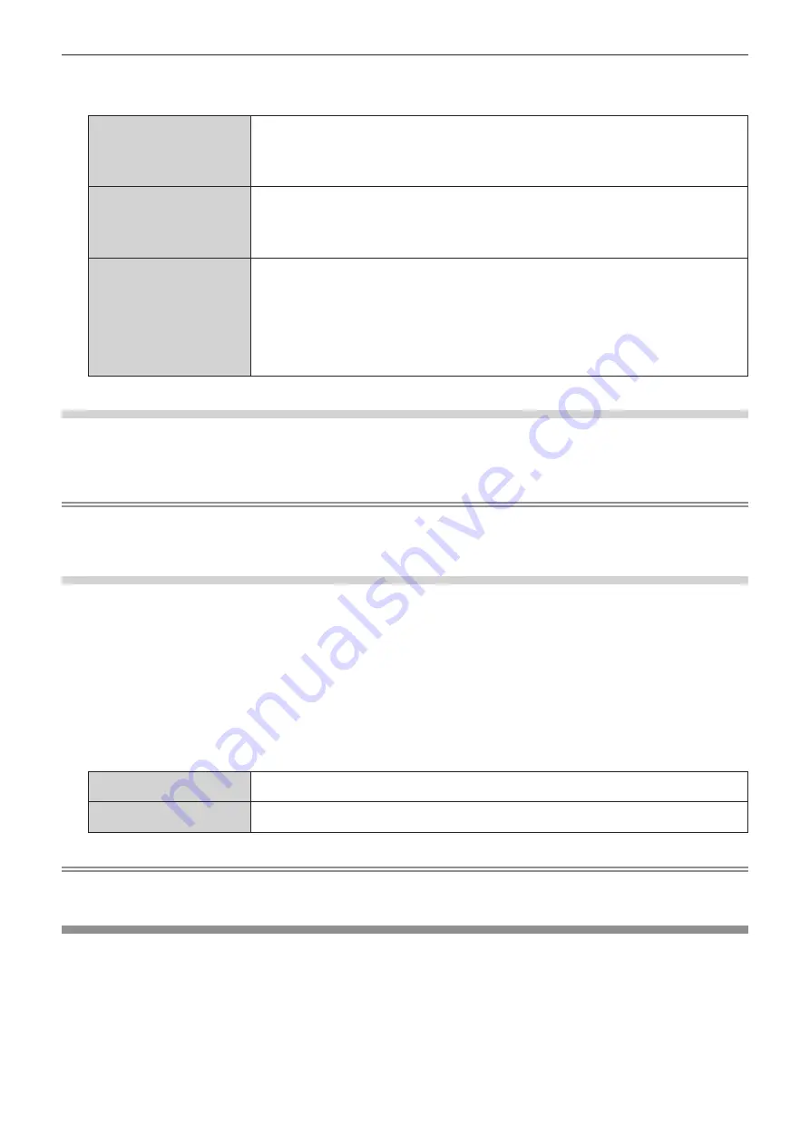
[OFF]
Select this item when connecting the optional DIGITAL LINK output supported device (Model No.:
ET-YFB100G, ET-YFB200G) to the <DIGITAL LINK/LAN> terminal.
[ON]
Select this item when connecting the “XTP transmitter” of Extron Electronics to the <DIGITAL LINK/
LAN> terminal.
Note
f
For details of the “XTP transmitter”, visit the website of Extron Electronics.
URL http://www.extron.com/
[WIRED LAN]
Perform the connection setting to use the wired LAN.
1) Press
as
to select [WIRED LAN].
2) Press the <ENTER> button.
f
The
[WIRED LAN]
screen is displayed.
3) Press
as
to select an item, and change the settings according to the operation instructions of the
menu.


