background image

DIGITAL LINK

“DIGITAL LINK” is a technology that uses a twisted-pair-cable to transmit video, audio, Ethernet, and serial control 

signals. It is developed based on the communication standard of HDBaseT

TM

 established by HDBaseT Alliance 

and added with other features of Panasonic.

This projector supports the optional Panasonic DIGITAL LINK output compatible device (Model No.: ET-YFB100G, 

ET-YFB200G) and peripheral devices by other manufacturers (twisted-pair-cable transmitters such as the “XTP 

transmitter” of Extron Electronics) that use the same HDBaseT

TM

 standard. For the devices of other manufacturers 

that the operation has been verified with this projector, visit the Panasonic website (https://panasonic.net/cns/

projector/). Note that the verification for devices of other manufacturers has been made for the items set by 

Panasonic Corporation, and not all the operations have been verified. For operation or performance problems 

caused by the devices of other manufacturers, contact the respective manufacturers.

Early Warning Software

The projector supports “Early Warning Software”, which monitors the status of the display devices (projector or 

flat panel display) and the peripheral devices inside an intranet, and notifies of abnormality of such equipment and 

detects signs of possible abnormality. Also, maintenance can be performed in advance, because this software 

gives notification of approximate time to replace consumables of the display, to clean each part of the display, and 

to replace the components of the display.
Depending on the type of license, the number of displays that can be registered for monitoring varies. Limited to 

the first 90 days after installation in a computer, it is possible to register up to 2048 units of displays free of charge.
Download the software from the Panasonic website (https://panasonic.net/cns/projector/pass/). It is necessary to 

register and login to PASS

*1

 to download.

*1 PASS: Panasonic Professional Display and Projector Technical Support Website
Visit the Panasonic website (https://panasonic.net/cns/projector/pass/) for details. 

Storage

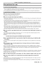
When storing the projector, keep it in a dry room.

Disposal

To dispose of the product, ask your local authorities or dealer for correct methods of disposal.
The luminous lamp contains mercury. When disposing of used lamp units, contact your local authorities or dealer 

for correct methods of disposal. 

Cautions on use


r

To get a good picture quality

In order to view a beautiful image in higher contrast, prepare an appropriate environment. Draw curtains or blinds 

over windows and turn off any lights near the screen to prevent outside light or light from indoor lamps from 
shining onto the screen.


r

Projection lens


f

Do not touch the surface of the projector lens with your bare hands.

If the surface of the lens becomes dirty from fingerprints or anything else, this will be magnified and projected onto 

the screen.
It is recommended to attach the supplied lens cap to the projection lens when you do not use the projector.


f

Do not wipe the lens during operation.

Cleaning the lens during operation may cause foreign objects adhering to the lens  

or bring damage to the lens surface.


r

LCD panel

The LCD panel is precision-made. Note that in rare cases, pixels could be missing or always lit. Note that such 

phenomena do not indicate malfunction. 
If still images are projected for a long time, a residual image may remain on the LCD panel. In this case, project 

the all white screen for over an hour. Note that the residual image may not disappear. 

Indicated on the projector

ENGLISH


-


23

Chapter 1  Preparation - Precautions for use

Summary of Contents for PT-VZ585N

Page 1: ...t This manual is intended for products manufactured from Aug 2018 and beyond Before operating this product please read the instructions carefully and save this manual for future use Before using your...

Page 2: ...ng 51 Selecting the image input for projection 51 How to adjust the state of the image 53 Adjusting adjustable feet 54 Adjusting the projection position with the optical axis shift function 54 Using t...

Page 3: ...PLICATION 133 Available application software 133 Connecting the devices 133 Terminating connection with the device 133 Idle screen descriptions 133 Using the moderator mode of Panasonic APPLICATION 13...

Page 4: ...defeat the purpose of the earthing plug WARNING This equipment is compliant with Class A of CISPR32 In a residential environment this equipment may cause radio interference WARNING TO REDUCE THE RISK...

Page 5: ...Equipment ANSI NFPA 75 For permanently connected equipment a readily accessible disconnect device shall be incorporated in the building installation wiring For pluggable equipment the socket outlet sh...

Page 6: ...must accept any interference received including interference that may cause undesired operation of this device This transmitter must not be co located or operated in conjunction with any other antenna...

Page 7: ...d or subject the Wireless LAN Module to strong impacts Do not disassemble or alter the Wireless LAN Module in any way Do not attempt to install the Wireless LAN Module in any incompatible device Do no...

Page 8: ...amp socket If a new plug is to be fitted please observe the wiring code as shown below If in any doubt please consult a qualified electrician WARNING THIS APPLIANCE MUST BE EARTHED IMPORTANT The wires...

Page 9: ...rojector for an extended period of time pull the power plug out from the wall outlet Pull the power plug out from the wall outlet and wipe it with a dry cloth regularly Do not handle the power plug an...

Page 10: ...t bracket to prevent the projector from falling down ACCESSORIES Do not use or handle the batteries improperly and refer to the following Failure to observe this will cause burns batteries to leak ove...

Page 11: ...ng so can cause damage and burns to clothing z z Strong light is emitted from the projector s lens Do not place objects in front of the lens while the projector is being used Doing so can cause fire d...

Page 12: ...Ask your dealer about replacing the lamp unit and check the inside of the projector When not using the projector for an extended period of time remove the batteries from the remote control Failure to...

Page 13: ...r expostas a temperaturas superiores a 100 C 212 F O g s liberado pela bateria pode irritar a garganta danificar o lacre do inv lucro ou o vazamento provocar calor ruptura da blindagem e produzir fogo...

Page 14: ...Panasonic Marketing Europe GmbH Panasonic Testing Centre Winsbergring 15 22525 Hamburg Germany El uso de este dispositivo con la banda de frecuencias de 5 GHz est restringido a espacios interiores en...

Page 15: ...lands Dit apparaat voldoet aan de essentiele eisen en andere van toepassing zijnde bepalingen van de Richtlijn 2014 53 EU Norsk Dette utstyret er i samsvar med de grunnleggende krav og andre relevante...

Page 16: ...ctivity or AVC VC 1 MPEG 4 video acquired from the licensed provider For details refer to the website of MPEG LA LLC http www mpegla com f f Other names company names or product names used in these op...

Page 17: ...e greatly reduced the maintenance time and the cost Multi device Connect Extensions With the image transfer application software you can project the screen of various devices easily via the wireless L...

Page 18: ...Chapter 1 Preparation This chapter describes things you need to know or check before using the projector 18 ENGLISH...

Page 19: ...n installing the product to a ceiling This requires an optional ceiling mount bracket Be sure to use the Projector Mount Bracket together with the ceiling mount bracket for high ceilings or low ceilin...

Page 20: ...installation use the four screw holes for ceiling mount as shown in the figure to fix the projector to the mount For details about the screw hole position for ceiling mount refer to Screw hole specif...

Page 21: ...rd in case you receive such an inquiry f f The connecting network must be secured by firewall or others f f Set a password for web control function appropriately and restrict the users who can log in...

Page 22: ...as those used in factory manufacturing lines etc f f Designated low power radio stations r r If at all possible avoid the use of cellular phones TV sets or radios near the projector Cellular phones TV...

Page 23: ...register up to 2048 units of displays free of charge Download the software from the Panasonic website https panasonic net cns projector pass It is necessary to register and login to PASS 1 to downloa...

Page 24: ...vidual differences and usage conditions In particular continuous use for 12 hours or more and frequent off on switching of the power greatly deteriorate the luminous lamp and affect the luminous lamp...

Page 25: ...projector at the time of purchase RGB signal cable 1 K1HY15YY0012 Attention f f After unpacking the projector discard the power cord cap and packaging material properly f f Do not use the supplied pow...

Page 26: ...via wireless LAN By pairing the commercially available USB memory with the projector easy wireless connection can be achieved For details of the pairing between the projector and the USB memory refer...

Page 27: ...e 62 7 Input selection buttons MEMORY VIEWER MIRRORING Panasonic APP COMPUTER 1 COMPUTER 2 VIDEO HDMI 1 HDMI 2 DIGITAL LINK Switches the input signal to project page 51 8 Number 1 6 buttons Used for e...

Page 28: ...d the remote control signal receiver the remote control may not operate correctly f f You can operate the projector by reflecting the remote control signal on the screen The operating range may differ...

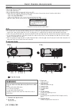
Page 29: ...cator ON G STANDBY R Displays the status of the power 3 Lamp indicator LAMP Displays the status of the luminous lamp 4 Temperature indicator TEMP Displays the status of the internal temperature 5 Ambi...

Page 30: ...ach the USB memory when using the Memory Viewer function or the Pairing function pages 140 147 6 DIGITAL LINK LAN terminal This is a terminal to connect a device that transfer video signal or audio si...

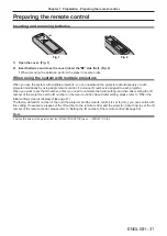
Page 31: ...first you need to complete the Initial setting and then after setting the ID number of the projector set the ID number on the remote control About Initial setting please refer to When the initial set...

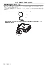
Page 32: ...loss of the lens cap please attach the lens cap with the string of accessories according to the following procedures 1 Thread the thinner end of the string through the hole on the lens cap Lens cap S...

Page 33: ...Chapter 2 Getting Started This chapter describes things you need to do before using the projector such as the setup and connections ENGLISH 33...

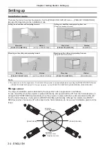
Page 34: ...ojector is automatically detected by setting the PROJECTOR SETUP menu PROJECTION METHOD to AUTO For rear projection set the PROJECTION METHOD to REAR DESK or REAR CEILING rAngle sensor The range of in...

Page 35: ...n you install the bracket and the projector Attention f f To ensure projector performance and security installation of the ceiling mount bracket must be carried out by your dealer or a qualified techn...

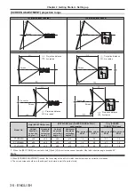
Page 36: ...ction angle Horizontal keystone correction angle Vertical keystone correction angle Horizontal keystone correction angle Min value of R2 L2 Min value of R3 L3 Min value of R2 L2 Min value of R3 L3 PT...

Page 37: ...5 0 169 1 524 6 35 250 5 92 9 56 0 187 1 683 6 09 9 83 0 019 1 556 6 71 10 83 0 212 1 905 7 62 300 7 11 11 48 0 224 2 019 7 31 11 80 0 023 1 867 8 05 13 00 0 254 2 286 For PT VW545N Unit m Projection...

Page 38: ...381 1 905 6 52 10 57 0 104 1 556 6 34 10 29 0 067 1 683 7 62 300 7 18 11 65 0 457 2 286 7 82 12 70 0 124 1 867 7 61 12 35 0 081 2 019 Projection distance formulas To use a projected image size not li...

Page 39: ...es containing too much jitter may cause the images on the screen to randomly wobble or wafture In this case a time base corrector TBC must be connected f f The projector supports VIDEO signals YCB CR...

Page 40: ...s not conform to HDMI standards is used images may be interrupted or may not be displayed f The HDMI 1 IN terminal HDMI 2 IN terminal can be connected to an external device with the DVI D terminal by...

Page 41: ...cable that conforms to the HDMI standards If a cable that does not conform to the HDMI standards is used images may be interrupted or may not be projected f f If you operate the projector using the c...

Page 42: ...llowing criteria g g Compatible with CAT5e or higher g g Shielded type including connectors g g Straight through g g Single wire f f When laying cables between a twisted pair cable transmitter and the...

Page 43: ...reach video signal or distance that can be transmitted may be restricted depending on the specification of the twisted pair cable transmitter f f For twisted pair cable transmitter of other manufactu...

Page 44: ...Chapter 3 Basic Operations This chapter describes basic operations to start with 44 ENGLISH...

Page 45: ...f the projector body and the power cord connector and insert the plug completely in the correct direction until you hear the side tabs click in place Removing the power cord 1 Confirm that the project...

Page 46: ...ector is preparing to be switched off The power will be switched off after a while Changes to the standby mode 1 The indicator flashes in the cycle 2 75 seconds light 0 25 seconds off 2 The indicator...

Page 47: ...y display the menu screen it may be necessary to adjust the focus lever and the zoom lever in the projection lens area of the projector page 28 For details refer to How to adjust the state of the imag...

Page 48: ...hange the setting from the DISPLAY OPTION menu SCREEN SETTING SCREEN FORMAT SCREEN POSITION 1 Press as to select the SCREEN FORMAT 2 Press qw to select the aspect ratio 3 Press as to select the SCREEN...

Page 49: ...enu INITIALIZE ALL is executed the INITIAL SETTING screen is displayed after projection starts Refer to When the initial setting screen is displayed page 47 Switching off the projector 2 1 3 2 1 1 Pre...

Page 50: ...ing so may cause the lamp fail to light while you powering on the projector next time or result in premature deterioration of the luminous lamp Note f f If the PROJECTOR SETUP menu INITIAL STARTUP is...

Page 51: ...s recorded in the USB memory can be displayed page 140 MIRRORING MIRRORING Switches the input to MIRRORING Using the MIRRORING function the images transferred via wireless LAN can be displayed from de...

Page 52: ...ss is to write the image transfer application software Plug and Share and the connection information between the projector and the USB memory to the USB memory f f For details of the image transfer ap...

Page 53: ...f f Place the projector on a level surface and make its front side parallel to the screen surface so that the projection screen is rectangular f f If the projector is facing downward with respect to...

Page 54: ...ing the projection position with the optical axis shift function This projector is equipped with vertical optical axis shift function The projection position can be adjusted in the range shown in the...

Page 55: ...the USB memory from the projector while reading or writing data USB memory that can be used with the projector The projector supports commercially available USB memory formatted with FAT16 or FAT32 No...

Page 56: ...e image and audio turn on Using the mute function This button allows you to turn off the audio output temporarily button 1 Press the MUTE button f f The audio turns off 2 Press the MUTE button again f...

Page 57: ...e image or a dark image it may not be able to be adjusted correctly even if the automatic adjustment is performed In this case adjust the following settings g g POSITION menu DOT CLOCK page 74 g g POS...

Page 58: ...tton Note f f When using the digital zoom function the magnification can be set from 1 0x to 3 0x with 0 1 increments when the D ZOOM button D ZOOM button is pressed f f When the image enlarged to 1 1...

Page 59: ...number to the remote control The factory default ID number of the projector is set to ALL When using a single projector press the ID ALL button on the remote control Also you can control a projector b...

Page 60: ...Chapter 4 Settings This chapter describes the settings and adjustments you can make using the on screen menu 60 ENGLISH...

Page 61: ...R ADJUSTMENT COLOR CORRECTION AUTO AUTO AUTO ON OFF OFF BLUE DEFAULT LOGO ON SCREEN DISPLAY HDMI SIGNAL LEVEL DIGITAL LINK SIGNAL LEVEL CLOSED CAPTION SETTING SCREEN SETTING STARTUP LOGO AUTO SETUP SE...

Page 62: ...er to Main menu page 62 and Sub menu page 63 Resetting adjustment values to the factory default If the DEFAULT button on the remote control is pressed the values adjusted in the menu items are restore...

Page 63: ...input signal POSITION Sub menu item Factory default Page REALTIME KEYSTONE ON 70 SCREEN ADJUSTMENT 70 SHIFT 73 DOT CLOCK 0 74 CLOCK PHASE 0 74 OVER SCAN 0 1 75 ASPECT NORMAL 1 75 FRAME LOCK ON 76 1 It...

Page 64: ...MENU LOCK PASSWORD 96 CONTROL DEVICE SETUP 97 NETWORK USB Sub menu item Factory default Page DIGITAL LINK MODE AUTO 98 DIGITAL LINK STATUS 98 DIGITAL LINK MENU 98 WIRED LAN 99 WIRELESS LAN SIMPLE 100...

Page 65: ...for use in a dark room 1 Only for the movie based signals 2 Only for the still image signals CONTRAST You can adjust the contrast of the colors 1 Press as to select CONTRAST 2 Press qw or the ENTER b...

Page 66: ...individual adjustment screen is displayed 3 Press qw to adjust the level Operation Adjustment Adjustment range Press the w button Contours become sharper 0 15 Press the q button Contours become softer...

Page 67: ...played 3 Press qw to switch the item f f The items will switch each time you press the button ON Corrects the vividness of the image OFF No correction AUTO Detects the brightness of the installation e...

Page 68: ...AL60 and SECAM f f Set it to AUTO normally Setting AUTO will automatically select NTSC NTSC4 43 PAL PAL M PAL N SECAM or PAL60 RGB YCB CR RGB YPB PR The projector will automatically detect the input s...

Page 69: ...f The selectable items differ depending on the input signal Items Resolution dots Scanning frequency Dot clock frequency MHz Horizontal kHz Vertical Hz 1280x768 60 1 280 x 768 47 7 60 0 80 1 1366x768...

Page 70: ...USTMENT Correct the distortion when the projector is installed as tilted or the screen is tilted or curved 1 Press as to select SCREEN ADJUSTMENT 2 Press the ENTER button f f The SCREEN ADJUSTMENT scr...

Page 71: ...e obtained by dividing the actual projection distance by the projection screen width KEYSTONE H V BALANCE Note f f Pressing the ENTER button while the individual adjustment screen is displayed can swi...

Page 72: ...SCREEN ADJUSTMENT screen is displayed 3 Press as to select CURVED CORRECTION 4 Press the ENTER button f f The CURVED CORRECTION screen is displayed 5 Press as to select the item to adjust 6 Press the...

Page 73: ...ton while the individual adjustment screen is displayed can switch to the individual adjustment screen of other items SHIFT Only for COMPUTER1 COMPUTER2 signal input Move the image position vertically...

Page 74: ...least 1 Press as to select DOT CLOCK 2 Press qw or the ENTER button f f The DOT CLOCK individual adjustment screen is displayed 3 Press qw to adjust f f The adjustment values are 32 to 32 Attention f...

Page 75: ...aspect ratio selected in SCREEN FORMAT the images are displayed with the right and left parts cut off FULL Displays images to the full screen range selected in SCREEN FORMAT If the aspect ratio of the...

Page 76: ...CK individual adjustment screen is displayed 3 Press qw to switch the item f f The items will switch each time you press the button ON The frame is locked Synchronizes the displayed image to the verti...

Page 77: ...CURITY NETWORK USB ENTER SELECT RETURN ASSIGNED FUNCTION DISABLE 1 2 f f Various menus settings adjustment screens control button names etc are displayed in the selected language f f The language can...

Page 78: ...test pattern for the selected color is displayed 6 Press as to select RED GREEN or BLUE f f GAIN can be adjusted when WHITE is selected in Step 4 7 Press qw to adjust f f The adjustment value changes...

Page 79: ...is added to or subtracted from the adjustment color When correction color green is changed Green is added to or subtracted from the adjustment color When correction color blue is changed Blue is added...

Page 80: ...h this setting the display position of the individual adjustment screen also changes 1 Press as to select ON SCREEN DISPLAY 2 Press the ENTER button f f The ON SCREEN DISPLAY screen is displayed 3 Pre...

Page 81: ...such as a blu ray player is connected to the HDMI 1 IN terminal HDMI 2 IN terminal 0 1023 Select when the DVI terminal output of an external device such as a computer is connected to the HDMI 1 IN te...

Page 82: ...ss qw to switch the item f f The items will switch each time you press the button CC1 Displays CC1 data CC2 Displays CC2 data CC3 Displays CC3 data CC4 Displays CC4 data Note f f Closed caption is a f...

Page 83: ...ables the startup logo display Note f f The startup logo will disappear in approximately 30 seconds f f To create register the USER LOGO image use Logo Transfer Software included in the supplied CD RO...

Page 84: ...e mode 1 Press as to select P TIMER 2 Press the ENTER button f f The P TIMER screen is displayed 3 Press as to select MODE 4 Press qw to switch the item f f The items will switch each time you press t...

Page 85: ...erating the menu as an alternative of operating the remote control button Using the freeze function The projected image is paused temporarily and the sound is stopped regardless of the playback of the...

Page 86: ...agnification can be adjusted from 1 0 to 3 0 times with increments of 0 1 6 Press the ENTER button f f The operation guide is displayed at the lower left of the screen 7 Press asqw to move the enlarge...

Page 87: ...lamp unit replacement time rough estimate A 1 B 5 6 C 5 7 f f A The luminous lamp runtime when LAMP POWER is set to NORMAL f f B The luminous lamp runtime when LAMP POWER is set to ECO1 f f C The lumi...

Page 88: ...eaker STANDBY Starts up in the standby mode ON Starts the projection immediately PROJECTION METHOD Set the projection method in accordance with the installation status of the projector Change the proj...

Page 89: ...tting 5 Press as to select one item AMBIENT LIGHT DETECTION Adjusts the power of the luminous lamp according to the brightness of the installation location SIGNAL DETECTION Lowers the power of the lum...

Page 90: ...f The items will switch each time you press the button NORMAL Select this item to use the network function during standby ECO Select this item to reduce power consumption during standby Note f f When...

Page 91: ...ies DZ680 series DW640 series DX610 series DW730 series DX800 series DZ6710 series DZ6700 series DW6300 series D6000 series D5000 series DZ570 series DW530 series DX500 series RZ970 series RW930 serie...

Page 92: ...ss as to select IN STANDBY MODE 4 Press qw to switch the item f f The items will switch each time you press the button OFF Disables audio output in the standby mode ON Enables audio output in the stan...

Page 93: ...from the PICTURE menu will not be re ected in the test pattern Make sure to perform various adjustments with input signals displayed 1 Press as to select TEST PATTERN 2 Press the ENTER button f f The...

Page 94: ...The display of FILTER COUNTER changes to 0H INITIALIZE ALL Return various setting values to their factory default settings 1 Press as to select INITIALIZE ALL 2 Press the ENTER button 3 When the INIT...

Page 95: ...ect PASSWORD 2 Press qw to switch the item f f The items will switch each time you press the button OFF Disables the security password entry ON Enables the security password entry Note f f The factory...

Page 96: ...u operations ON Disables menu operations Note f f The factory default setting or the setting after executing the PROJECTOR SETUP menu INITIALIZE ALL is set to OFF Set it to ON if necessary f f When ME...

Page 97: ...l buttons DISABLE Disable the operation of all buttons f f When you change ENABLE to DISABLE proceed to Step 5 5 When the confirmation screen is displayed press qw to select OK and then press the ENTE...

Page 98: ...20 x 1 080 dots dot clock frequency 148 5 MHz f f When the communication method of the twist pair cable transmitter is set to long reach the projector will connect with long reach communication method...

Page 99: ...he preferred DNS server address when DHCP is set to OFF DNS2 Enter the alternate DNS server address when DHCP is set to OFF EAP Select the EAP setup in the RADIUS server If EAP is not setup set it to...

Page 100: ...o and Brazil Note f f When set to SIMPLE or M DIRECT up to 10 devices supported by the projector can be connected simultaneously via wireless LAN f f Even if WIRELESS LAN is set to SIMPLE or M DIRECT...

Page 101: ...the radio waves of the wireless LAN supported device can reach f f KEY may be displayed as the password of SSID depending on the device f f The authentication method is fixed to WPA2 PSK and the encry...

Page 102: ...is TKIP It can be selected when AUTHENTICATION is set to WPA PSK WPA2 PSK WPA EAP or WPA2 EAP AES Select this item when you use AES for the encryption method It can be selected when AUTHENTICATION is...

Page 103: ...he access point even after executing Projector settings page 112 consult the manufacturer of your access point radio repeater f f If USER is used you cannot connect to the access point of stealth SSID...

Page 104: ...select Panasonic APPLICATION 2 Press the ENTER button f f The Panasonic APPLICATION screen is displayed 3 Press as to select the MODERATOR MODE 4 Press qw to switch the item f f The item will switch e...

Page 105: ...Panasonic APPLICATION 2 Press the ENTER button f f The Panasonic APPLICATION screen is displayed 3 Press as to select PASSWORD 4 Press qw to switch the items f f The item will switch each time you pre...

Page 106: ...hen the Panasonic APPLICATION input is selected f f For methods of pairing the projector and the USB memory refer to Using the Pairing function page 147 f f On how to handle the USB memory refer to Us...

Page 107: ...qw to select the item f f The items will switch each time you press the button OFF Disables the moderator mode function Only one device screen can be displayed among the devices connected to the proj...

Page 108: ...lays the whole gradually BLIND Displays gradually to open a vertical blind CHECKER WIPE Displays gradually to the right from the left side in a grid pattern SLIDE IN Displays the next screen to appear...

Page 109: ...cter string of SSID AUTHENTICATION Displays the user authentication method EAP Displays the type of EAP ENCRYPTION Displays the encryption method DEFAULT KEY Displays the number of the default key DHC...

Page 110: ...Chapter 5 Operation of Function This chapter describes the operation methods of some functions 110 ENGLISH...

Page 111: ...transfer application software Plug and Share which allows easy wireless connection by pairing the commercially available USB memory with the projector refer to the Operating Instructions of Plug and...

Page 112: ...hen laying cables between a twisted pair cable transmitter and the projector check that cable characteristics are compatible with CAT5e or higher using tools such as a cable tester or cable analyzer W...

Page 113: ...EFAULT GATEWAY 192 168 10 1 DNS1 DNS2 Blank Operating the computer 1 Turn on the power of the computer 2 Perform the network setting following the instruction of your network administrator f f If the...

Page 114: ...r 2 Select the NETWORK USB menu WIRELESS LAN from the main menu and set it to other than DISABLE 3 Press the ENTER button f f The WIRELESS DETAILED SETUP screen is displayed 4 Perform the connection s...

Page 115: ...mputer to Obtain an IP address automatically f f When the NETWORK USB menu WIRELESS LAN is set to USER make the network settings for the computer and the projector following the instructions of your n...

Page 116: ...wnload RoomView Express go to the website of Crestron Electronics Inc English only URL http www crestron com getroomview Computer that can be used for setting A web browser is required to use the web...

Page 117: ...ay of the screens in this manual may differ depending on the type of the OS the web browser or the computer you use Available functions per account The administrator rights allow use of all functions...

Page 118: ...projector 3 MAIN VERSION Displays the firmware version of the projector 4 POWER Displays the status of the power 5 PICTURE MODE Displays the status of the picture mode 6 SERIAL NUMBER Displays the ser...

Page 119: ...t fan FAN POWER Trouble has occurred in the power fan INTAKE AIR TEMPERATURE The environment temperature is too high Use under the proper operating environment temperature 1 EXHAUST AIR TEMPERATURE Th...

Page 120: ...RE MODE Switches the picture mode 4 AV MUTE Switches the status of AV mute ON the AV mute function is enabled OFF the AV mute function is disabled 5 POWER Turns on off the power 6 CLOSED CAPTION Switc...

Page 121: ...or details refer to the POSITION menu SHIFT x page 73 2 PICTURE Adjusts the image quality related items For details refer to PICTURE menu x page 65 Network config page Click Detailed set up Network co...

Page 122: ...ck the Submit button to update the setting 9 User name Enter the user name with alphanumeric characters excluding spaces up to 64 characters for authentication purpose 10 Password Enter the password w...

Page 123: ...r 8 to 63 ASCII characters or a 64 digit string in the hexadecimal format 6 Back Next Click the Back button to return to the original screen The setting confirmation screen is displayed by pressing th...

Page 124: ...2 Back Next Click the Back button to return to the previous screen The setting confirmation screen is displayed by pressing the Next button Click the Submit button to update the settings 13 KEY Set th...

Page 125: ...be sent to the preset E mail addresses up to two addresses Click Detailed set up E mail set up 1 2 3 4 5 6 1 ENABLE Select Enable to use the E mail function 2 SMTP SERVER NAME Enter the IP address or...

Page 126: ...it through E mail Authentication set up page Set the authentication items when POP authentication or SMTP authentication is necessary to send an E mail Click Detailed set up Authentication set up 1 2...

Page 127: ...RATURE OK LAMP REMAIN TIME OK LAMP STATUS OK APERTURE CONTRAST SHUTTER OK AIR FILTER OK Error code 00 00 00 00 00 00 00 00 Intake air temperature 31 degC 87 degF Exhaust air temperature 37 degC 98 deg...

Page 128: ...E 750 H LAMP NORMAL 100 H LAMP ECO1 420 H LAMP ECO2 420 H LAMP REMAIN 4250 H Current status MAIN VERSION 1 00 NETWORK VERSION 1 00 SUB VERSION 1 00 LAMP STATUS LAMP ON INPUT RGB Wired Network configur...

Page 129: ...input or Panasonic APPLICATION input is selected Administrator account 1 2 3 4 1 Account Displays the account to change 2 Current User name Enter the user name before the change Password Enter the cur...

Page 130: ...OK Confirm the change of password Note f f To change the account of the administrator you must enter the User name and Password in Current Crestron Connected TM page The projector can be monitored con...

Page 131: ...ntrols items related to freeze image quality 7 Back Returns to the previous page Tools page Click Tools on the control page 1 2 3 4 5 1 Control System Set the information required for communicating wi...

Page 132: ...lays the status of the power 5 Source Displays the selected input 6 Lamp Mode Displays the setting status of LAMP POWER page 88 7 Error Status Displays the error status 8 Exit Returns to the control p...

Page 133: ...ing function page 147 Connecting the devices 1 Press the Panasonic APP button f f The input switches to Panasonic APPLICATION and the idle screen is displayed f f The idle screen differs depending on...

Page 134: ...CANCEL is pressed Note f f QR code is used when connecting to the projector with the Wireless Projector r r When WIRELESS LAN is set to other than SIMPLE 1 2 1 Network ID Projector name Displays the n...

Page 135: ...plication software f f For details about the moderator mode setting refer to NETWORK USB menu Panasonic APPLICATION page 104 f f When you press the ENTER button while the image is projected in full sc...

Page 136: ...u set the NETWORK USB menu MIRRORING CONNECTION TYPE to PIN you may be prompted to enter the PIN when connecting In that case enter the eight digit PIN code displayed at the top of the idle screen f f...

Page 137: ...it PIN code displayed at the top of the idle screen 4 Press as to select the desired device to connect and press the ENTER button f f Select the device screen to be projected with the projector from t...

Page 138: ...wser from the moderator s device f Perform the Step 3 on the moderator s device as well f For information about the available browsers refer to Computer that can be used for setting page 116 6 Enter t...

Page 139: ...es the display language Japanese or English 3 Device list Click on the device name and the device screen is projected Note f The user name and the password of the moderator account can be changed on t...

Page 140: ...MP3 AAC Linear PCM mp4 H 264 MPEG 4 AVC MPEG 4 AAC MPEG 4 AAC LC mpg mpeg MPEG 2 MPEG 1 2 Audio Layer 2 wmv WMV9 WMA 1 Following movie files are not supported f f Files with the video codec of WMV7 W...

Page 141: ...n is displayed For thumbnail view 1 Press asqw to select a file f f When you select a folder in the thumbnail view area and press the ENTER button the files in the folder are displayed f f When you pr...

Page 142: ...with the as buttons and press the ENTER button the files in that folder are displayed in the list view area and the cursor moves to the list view area f f The thumbnail of the selected still image or...

Page 143: ...d continues automatic playback from the next file f f Pressing q during playback returns playback to the previous file and continues automatic playback f f Pressing a during playback rotates the image...

Page 144: ...playback is enabled This section describes the operations when the NETWORK USB menu MEMORY VIEWER AUTOPLAY x page 108 is set to ON In this case all movie files in the same folder are played back autom...

Page 145: ...MEMORY VIEWER GUIDE is set to OFF x page 109 1 The maximum number of display dots for each model is as follows PT VZ585N 1 920 x 1 080 PT VW545N 1 280 x 800 PT VX615N 1 024 x 768 Resume playback When...

Page 146: ...erclockwise Rotates the still image 90 clockwise Indicates that fast forward playback is being performed in approximately x2 speed with audio Indicates that fast forward playback is being performed in...

Page 147: ...emory cannot be directly attached to the USB A VIEWER terminal of a ceiling mounted projector you can download the image transfer application software Plug and Share from the Panasonic website to the...

Page 148: ...isplayed with the image transfer application software Also you cannot use the pairing function while using the image transfer application software f f For the using method of the image transfer applic...

Page 149: ...Chapter 6 Maintenance This chapter describes methods of inspection when there are problems maintenance and replacement of the units ENGLISH 149...

Page 150: ...lights in green while the projector is in projection mode if there is no notification by lighting or blinking in red Temperature indicator TEMP Indicator status Lighting in red Blinking in red Blinki...

Page 151: ...e Air filter unit This section describes the maintenance of the air filter unit that is installed as standard on the projector The air filter unit is the same as the optional Replacement Filter Unit M...

Page 152: ...lter unit If it is not attached the projector will suck in dirt and dust causing a malfunction Performing maintenance of the air filter unit Fig 1 Fig 2 1 Wash the air filter unit Fig 1 i Soak the air...

Page 153: ...ng the air filter counter page 153 Note f f When using the projector be sure to attach the air filter unit If it is not attached the projector will suck in dirt and dust causing a malfunction Resettin...

Page 154: ...mp units Note f f The model numbers of accessories and optional accessories are subject to change without prior notice When to replace the lamp unit The lamp unit is a consumable component Since its b...

Page 155: ...mp unit f f Hold the handle of the lamp unit and take it straight out f f Do not remove screws other than the lamp unit fixing screws 4 Press in the new lamp unit while paying attention to the inserti...

Page 156: ...page 152 2 Install the optional Replacement Filter Unit Model No ET RFV410 to the projector f f Refer to Attaching the air filter unit page 153 3 Reset the air filter counter f f Refer to Resetting t...

Page 157: ...er will not output audio 39 41 56 92 56 85 56 92 92 39 41 Remote control does not work f f Are the batteries depleted f f Is the polarity of the batteries set correctly 31 f f Are there any obstructio...

Page 158: ...twisted pair cable transmitter and the projector or an external device correctly done f f Is DIGITAL LINK MODE set to AUTO DIGITAL LINK or LONG REACH Is it set to ETHERNET 98 f f Is the signal input i...

Page 159: ...jector Also is the device too far away from the projector f f The devices may not be able to connect properly after recovering from sleep or switching login users Turn off and on the wireless LAN or r...

Page 160: ...ce in use r r The image contents cannot be displayed f f When using in moderator mode the HDCP compliant DVD or copyright protected contents cannot be displayed r r Others f f Depending on the device...

Page 161: ...Chapter 7 Appendix This chapter describes specifications for the projector ENGLISH 161...

Page 162: ...f f 2 Error 2nd byte Indicates lamp errors and returns 0 2 3rd byte Indicates temperature errors and returns 0 2 4th byte Returns 0 5th byte Indicates filter errors and returns 0 2 6th byte Indicates...

Page 163: ...ample Response during protect mode random number section is undefined value NTCONTROL 1 23181e1e CR 3 Generate a 32 byte hash value from the following data using MD5 algorithm f f xxxxxx yyyyy zzzzzzz...

Page 164: ...e used by a third party use the protect mode Connecting method 1 Obtain the IP address and port number Initial set value 1024 of the projector and make a request for connection to the projector f f Ac...

Page 165: ...sending the command Such specifications are made from the viewpoint of security such as prevention of illegal operation of the projector by a malicious third party To send commands continuously make a...

Page 166: ...2C x page 90 must be set according to the connection method f f When connecting by a DIGITAL LINK compatible device set the PROJECTOR SETUP menu ECO MANAGEMENT STANDBY MODE x page 90 to NORMAL to cont...

Page 167: ...luminous lamp starts illuminating there may be a delay in response or the command may not be executed Try sending or receiving any command after 60 seconds f f When transmitting multiple commands be...

Page 168: ...ection VID RG1 RG2 HD1 HD2 DL1 PA1 MC1 MV1 VIDEO COMPUTER1 COMPUTER2 HDMI1 HDMI2 DIGITAL LINK Panasonic APPLICATION MIRRORING MEMORY VIEWER OFZ Freeze 0 1 Freeze function disabled off Freeze function...

Page 169: ...1 280 x 720 45 0 60 0 74 3 R Y H l 720 50p 1 280 x 720 37 5 50 0 74 3 R Y H l 1080 60i 1 920 x 1 080i 33 8 60 0 74 3 R Y H l 1080 50i 1 920 x 1 080i 28 1 50 0 74 3 R Y H l 1080 24p 1 920 x 1 080 27 0...

Page 170: ...1 600 x 1 200 75 0 60 0 162 0 R H l l 1680 x 1050 50 1 680 x 1 050 54 1 50 0 119 5 R H 1680 x 1050 60 3 65 2 60 0 147 1 R H 1680 x 1050 60 65 3 60 0 146 3 R H 1920 x 1080 50 1 920 x 1 080 55 6 49 9 14...

Page 171: ...terlaced signal f f When interlaced signals are connected flickering may occur on the projected image f f Even the above signals exist some image signals recorded in special method may not be displaye...

Page 172: ...ata and the address corresponding to the data distribution destination is called the IP address The same IP address cannot be used within the same LAN LAN Abbreviation for Local Area Network This is a...

Page 173: ...tion data The encryption key is created and notified only to the communicating user so the communication data cannot be decrypted by a third party WPA EAP WPA2 EAP Standard for the encryption method f...

Page 174: ...Lens PT VZ585N Manual zoom 1 6x Focus F 1 6 2 12 f 15 30 mm 24 64 mm PT VW545N PT VX615N Manual zoom 1 6x Focus F 1 6 1 9 f 15 31 mm 24 64 mm Luminous lamp 280 W UHM lamp Light output 1 PT VZ585N 5 0...

Page 175: ...V p p 75 COMPUTER 2 IN 1 OUT 1 set high density D Sub 15 p female monitor output compatible RGB signal 0 7 V p p 75 When G SYNC 1 0 V p p 75 HD SYNC TTL high impedance automatic positive negative pol...

Page 176: ...rope and CIS IEEE802 11b g n 2 412 GHz 2 472 GHz IEEE802 11a n 5 745 GHz 5 805 GHz Channels used MIRRORING mode For Europe and CIS IEEE802 11b g n 1 11 channel IEEE802 11a n 36 40 44 48 channel The po...

Page 177: ...920 x 1 200 f f Dot clock frequency 162 MHz or less f f PIAS Panasonic Intelligent Auto Scanning mode YCB CR YPB PR signal input f f Signal resolution 480i 576i to 1 920 x 1 080 f f Dot clock frequen...

Page 178: ...Dimensions Unit mm inch 104 6 4 1 8 63 8 2 1 2 332 0 13 1 16 389 0 15 5 16 250 0 9 27 32 125 0 4 29 32 337 0 13 9 32 Actual dimension may differ by product 178 ENGLISH Chapter 7 Appendix Dimensions...

Page 179: ...onic or the inappropriate choice of location for installation even if the warranty period of the projector has not expired f f Unused products must be removed promptly by a qualified technician f f Us...

Page 180: ...mode 34 IRIS 67 L Lamp indicator 29 150 LAMP POWER 88 LANGUAGE 77 List of compatible signals 169 M Main menu 62 Maintenance replacement 151 MEMORY VIEWER button Remote control 27 MEMORY VIEWER 108 Me...

Page 181: ...in the European Union If you wish to discard these items please contact your local authorities or dealer and ask for the correct method of disposal Product Information for Turkey only AEEE Y netmeli...

Reviews: