- 18 -
Service Manual
Disassembly for service
Note:
Board ground wires may have to be disconnected to disassemble some boards. All ground wires must be
reconnected using jumper leads, if necessary, before power is applied to PTV for service.
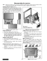
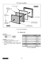
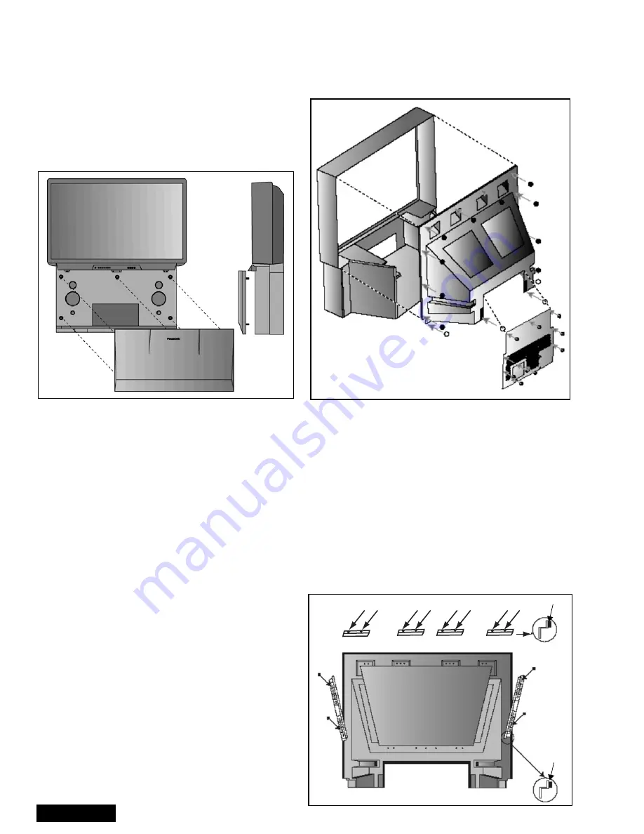
Speaker grille removal
(figure 11)
The speaker grille is secured to the cabinet of the PTV.
grip panel from the sides and middle upper part, gently
pull forward to remove. When reassembling, make
certain to firmly press on the panel where the insertion
points (5) are located, one at each corner and one at
the middle top edge.
Figure 11. Speaker grille removal.
Keyboard removal
1.
Remove the speaker grille. See figure 11.
2.
Unplug the connectors from the Keyboard and
front A/V inputs assemblies. Remove the screws
affixing the keyboard to the frame assembly. Tilt
the keyboard assembly upward and release it from
the screen frame assembly.
Speakers replacement
1.
Remove the speaker grille. See figure 11.
2.
Each speaker is secured to the cabinet with (4)
screws.
3.
Disconnect the R & L speaker lead connectors
from the speaker units.
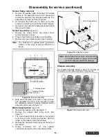
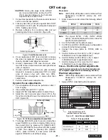
Cabinet back lower cover removal
(figure 12)
1.
Remove (7) hex screws around the perimeter,
marked with arrows. See figure 12 for screws
location.
2.
Remove (3) screws from around the A/V terminal
board (marked with arrows).
Figure 12. Lower cabinet back removal
Cabinet back cover removal
(figure 12)
1.
Remove the cabinet back lower cover. (Detailed
previously).
2.
The top back cover (plastic shell) is secured with
(14) screws around its perimeter. See figure 12 for
screws location.
3.
Be careful not to damage the mirror secured to the
underside of the back cover.
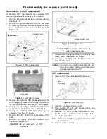
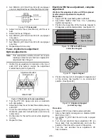
Mirror removal
(figure 13)
The mirror is attached inside the cabinet cover.
Carefully remove the cabinet cover to access its
interior surface and remove the screws securing the
brackets that hold the mirror at the top and sides to the
mirror. See figure 13.
Figure 13. Mirror removal
Screw count:
14 fasten the top back cover;
10 fasten the lower back cover
Screws (12 places)
Felt
Felt
Mirror
Brackets (4 places)
Bracket
(2 places)
cabinet cover
(Inside view)
Summary of Contents for PT47WX52F - 47" PROJECTION TV HD
Page 65: ... 65 Notes PARTS LIST ...
Page 66: ... 66 D Board Schematic ...
Page 67: ... 67 D Board Schematic ...
Page 68: ... 68 D Board Schematic ...
Page 69: ... 69 Jumper between pin 7 and pin 1 D Board Schematic ...
Page 70: ... 70 D Board Schematic ...
Page 71: ... 71 D Board Schematic ...
Page 73: ... 73 NOTES NOTES ...
Page 74: ... 74 D Board Layout ...
Page 75: ... 75 D Board Layout ...
Page 76: ... 76 A Board Schematic ...
Page 77: ... 77 A Board Schematic ...
Page 78: ... 78 A Board Schematic ...
Page 79: ... 79 A Board Schematic ...
Page 80: ... 80 A Board Schematic ...
Page 81: ... 81 A Board Schematic ...
Page 82: ... 82 A Board Schematic ...
Page 83: ... 83 A Board Schematic ...
Page 84: ... 84 Board section Top A Board Layout Top left portion ...
Page 85: ... 85 Board section Top A Board Layout Top right portion ...
Page 86: ... 86 Board section Top A Board Layout Bottom left portion ...
Page 87: ... 87 Board section Top A Board Layout Bottom right portion ...
Page 88: ... 88 Board section Bottom side A Board Layout Top left portion ...
Page 89: ... 89 Board section Bottom A Board Layout Top right portion ...
Page 90: ... 90 Board section Bottom A Board Layout Bottom left portion ...
Page 91: ... 91 Board section Bottom A Board Layout Bottom right portion ...
Page 92: ... 92 LG Board schematic TNP2AA112 LG Board schematic ...
Page 94: ... 94 LR Board schematic TNP2AA111 LR Board schematic ...
Page 96: ... 96 LB Board schematic TNP2AA110 LB Board schematic ...
Page 98: ... 98 K Board schematic TNP2AA089 K Board layout TNP2AA089 K Board schematic and layout ...
Page 99: ... 99 G Board schematic TNP2AA090 G Board layout TNP2AA090 G Board schematic and layout ...
Page 104: ...Printed in USA K02042127PL0429 ...


