- 26 -
Service Manual
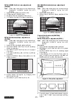
NTSC ZOOM Vertical size adjustment
(VSIZE)
Note:
1080i, 480p, 480i pattern can be obtained from
Panasonic’s
TU-DST51
set-top
box
DTV
decoder.
1.
Apply a NTSC pattern (see avobe note) .
2.
Change aspect to ZOOM mode.
3.
Repeat vertical size adjustment from step 2
4.
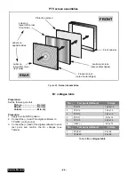
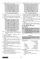
Try making circle seem rounded (in proportion)
NTSC Horizontal phase adjustment
(H-POS)
Note:
1080i, 480p, 480i pattern can be obtained from
Panasonic’s
TU-DST51
set-top
box
DTV
decoder.
1.
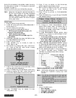
Apply a NTSC crosshatch pattern with dots.
2.
Set CONV “MUTE” DAC from 00 to 01 (disabling
digital convergence).
3.
Set VIDEO “C_OFF” DAC from 00 to 01 to project
only green.
4.
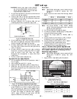
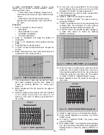
Turn green deflection yoke until line is perfectly
horizontal.
5.
Adjust H-POS DAC data so that pattern is in the
center of screen.
6.
Enable digital convergence by changing DAC
MUTE from 01 to 00.
7.
Set VIDEO “C_OFF” DAC from 01 to 00.
HD 1080i Horizontal phase adjustment
(H-POS)
Note:
1080i, 480p, 480i pattern can be obtained from
Panasonic’s
TU-DST51
set-top
box
DTV
decoder.
1.
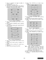
Apply a HD 1080i pattern.
2.
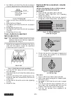
Repeat NTSC horizontal phase adjustment from
step 2.
Trapezoid adjustment (EWTRA)
1.
Set default value
NTSC Pincushion adjustment (PCC)
Note:
1080i, 480p, 480i pattern can be obtained from
Panasonic’s
TU-DST51
set-top
box
DTV
decoder.
Procedure:
1.
Apply a NTSC crosshatch pattern with dots.
2.
Set VIDEO “C_OFF” DAC from 00 to 01 to project
only green.
3.
Set DAC MUTE from 00 to 01 (disabling digital
convergence).
4.
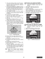
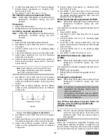
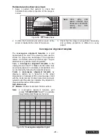
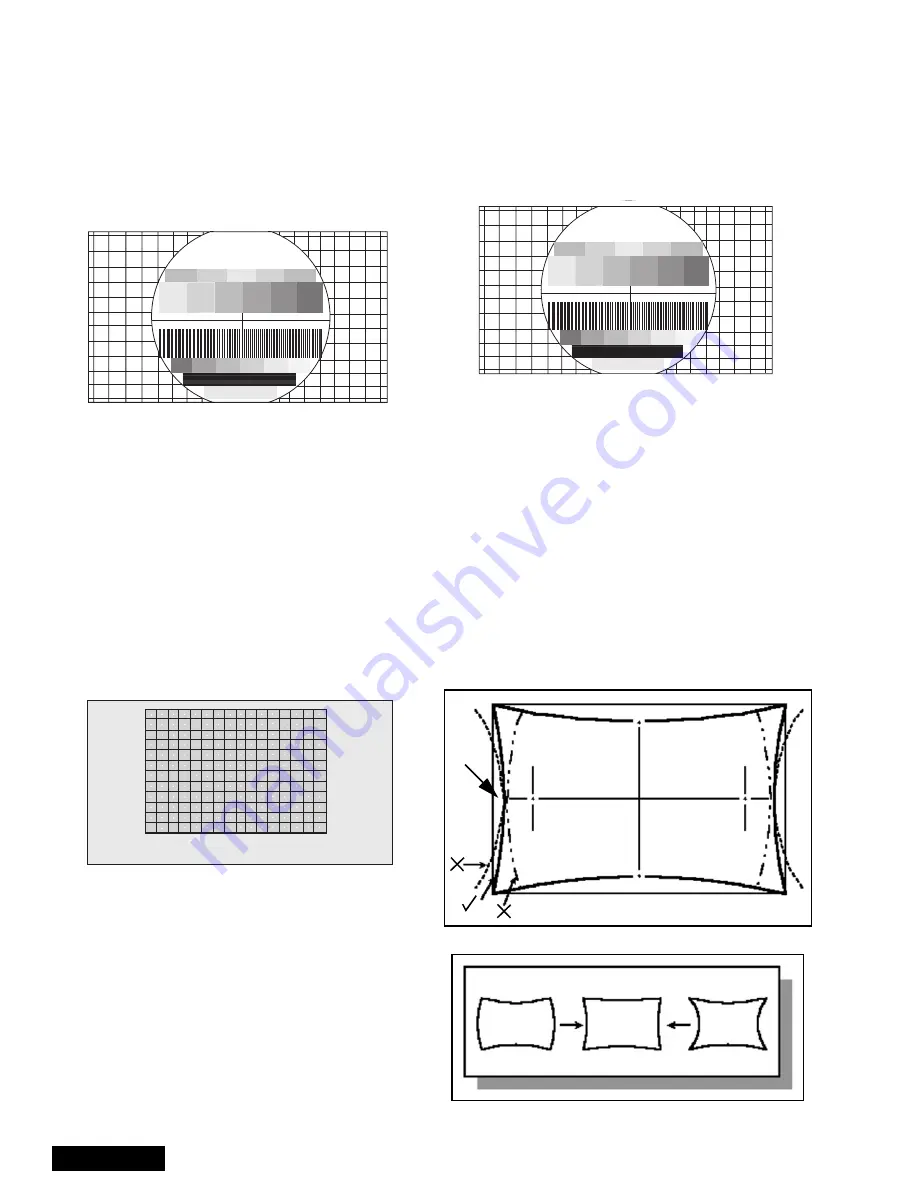
If the distance at “A” is not 10 ± 5mm, enter “H
DEF” “H WID” mode and adjust by VOLUME UP/
DOWN until it is 10 ± 5mm. See figure 39.
Figure 39. Pincushion adjustment
5.
If not all corners of cross hatch appear in screen,
enter V DEF “V SIZE” mode and adjust until they
appear.
Panasonic
FORMAT
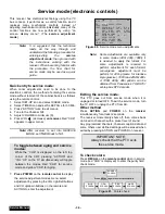
Figure 36. Vertical size adjustment
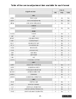
Figure 37. H phase adjustment
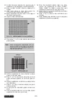
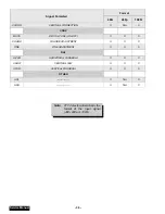
Figure 38. H Phase adjustment
Panasonic
FORMAT
Line with dot
A = 10 ± 5mm
A
NOT GOOD
GOOD
NOT GOOD
Summary of Contents for PT47WX52F - 47" PROJECTION TV HD
Page 65: ... 65 Notes PARTS LIST ...
Page 66: ... 66 D Board Schematic ...
Page 67: ... 67 D Board Schematic ...
Page 68: ... 68 D Board Schematic ...
Page 69: ... 69 Jumper between pin 7 and pin 1 D Board Schematic ...
Page 70: ... 70 D Board Schematic ...
Page 71: ... 71 D Board Schematic ...
Page 73: ... 73 NOTES NOTES ...
Page 74: ... 74 D Board Layout ...
Page 75: ... 75 D Board Layout ...
Page 76: ... 76 A Board Schematic ...
Page 77: ... 77 A Board Schematic ...
Page 78: ... 78 A Board Schematic ...
Page 79: ... 79 A Board Schematic ...
Page 80: ... 80 A Board Schematic ...
Page 81: ... 81 A Board Schematic ...
Page 82: ... 82 A Board Schematic ...
Page 83: ... 83 A Board Schematic ...
Page 84: ... 84 Board section Top A Board Layout Top left portion ...
Page 85: ... 85 Board section Top A Board Layout Top right portion ...
Page 86: ... 86 Board section Top A Board Layout Bottom left portion ...
Page 87: ... 87 Board section Top A Board Layout Bottom right portion ...
Page 88: ... 88 Board section Bottom side A Board Layout Top left portion ...
Page 89: ... 89 Board section Bottom A Board Layout Top right portion ...
Page 90: ... 90 Board section Bottom A Board Layout Bottom left portion ...
Page 91: ... 91 Board section Bottom A Board Layout Bottom right portion ...
Page 92: ... 92 LG Board schematic TNP2AA112 LG Board schematic ...
Page 94: ... 94 LR Board schematic TNP2AA111 LR Board schematic ...
Page 96: ... 96 LB Board schematic TNP2AA110 LB Board schematic ...
Page 98: ... 98 K Board schematic TNP2AA089 K Board layout TNP2AA089 K Board schematic and layout ...
Page 99: ... 99 G Board schematic TNP2AA090 G Board layout TNP2AA090 G Board schematic and layout ...
Page 104: ...Printed in USA K02042127PL0429 ...


