- 33 -
Service Manual
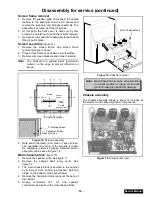
Horizontal and vertical size check
1.
Apply a pattern that permits to check that
horizontal and vertical proportion of the image is
correct.
2.
Confirm that horizontal and vertical center of the
picture is located in the center of the screen.
3.
Check that the image is proportional horizontally
and vertically, proportion is different on every
aspect.
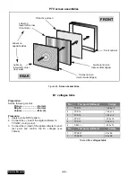
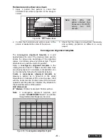
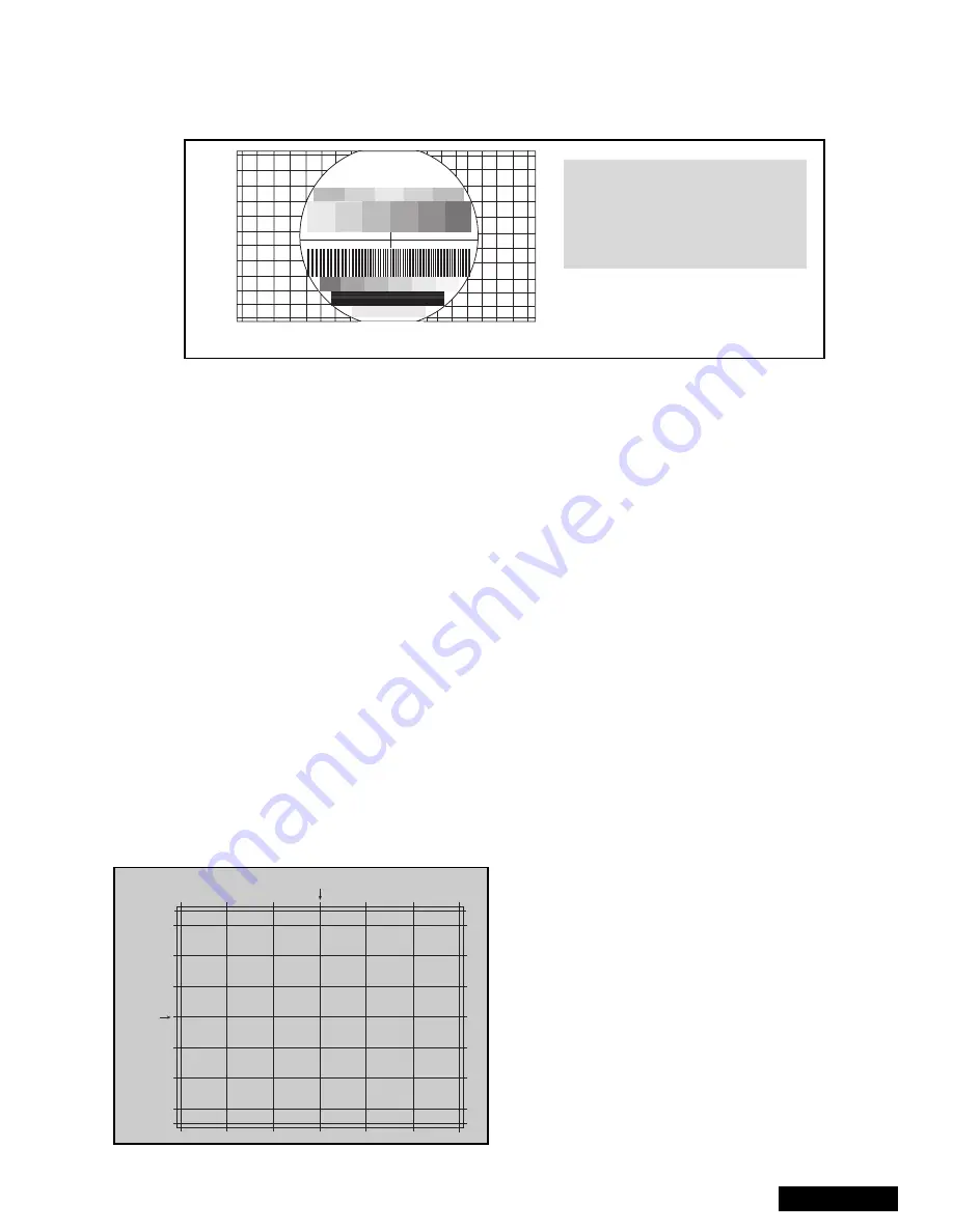
Convergence alignment template
The convergence alignment template is a grid
approximately the size of the viewing screen used to
ensure the proper size and shape of the alignment
rasters. It is 6 blocks across by 6 blocks high. The grid
dimensions vary with the mode of operation.
Apply a convergence alignment template to the
viewing screen of the PTV. Make sure the center lines
are properly aligned. If a template is not available, one
can be created by following the instructions below.
Create a
convergence alignment template by
drawing a pattern, as in figure 59, in the actual
dimensions on transparent film or tracing paper. Start
with the Horizontal and Vertical Center Axis and work
outwards until the pattern is complete. Pay attention to
the actual dimensions of the pattern.
Grid dimensions:
47” Models: 1036mm horizontal X 584mm vertical.
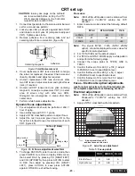
Note:
A
convergence
alignment
template,
part
number TXFQD01ESER1 for 47”, is available
through Matsushita/Panasonic Services.
Panasonic
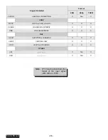
FORMAT
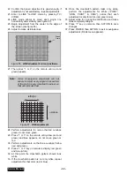
Figure 58. H & V size check
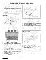
Note:
1080i,
480p,
480i
pattern obtained from
Panasonic’s TU-DST51
set-top
box
DTV
decoder.
1
1
1
2
2
3
2
3
3
3
2
1
Center
Center
Figure 59. Convergence adjustment grid
Summary of Contents for PT47WX52F - 47" PROJECTION TV HD
Page 65: ... 65 Notes PARTS LIST ...
Page 66: ... 66 D Board Schematic ...
Page 67: ... 67 D Board Schematic ...
Page 68: ... 68 D Board Schematic ...
Page 69: ... 69 Jumper between pin 7 and pin 1 D Board Schematic ...
Page 70: ... 70 D Board Schematic ...
Page 71: ... 71 D Board Schematic ...
Page 73: ... 73 NOTES NOTES ...
Page 74: ... 74 D Board Layout ...
Page 75: ... 75 D Board Layout ...
Page 76: ... 76 A Board Schematic ...
Page 77: ... 77 A Board Schematic ...
Page 78: ... 78 A Board Schematic ...
Page 79: ... 79 A Board Schematic ...
Page 80: ... 80 A Board Schematic ...
Page 81: ... 81 A Board Schematic ...
Page 82: ... 82 A Board Schematic ...
Page 83: ... 83 A Board Schematic ...
Page 84: ... 84 Board section Top A Board Layout Top left portion ...
Page 85: ... 85 Board section Top A Board Layout Top right portion ...
Page 86: ... 86 Board section Top A Board Layout Bottom left portion ...
Page 87: ... 87 Board section Top A Board Layout Bottom right portion ...
Page 88: ... 88 Board section Bottom side A Board Layout Top left portion ...
Page 89: ... 89 Board section Bottom A Board Layout Top right portion ...
Page 90: ... 90 Board section Bottom A Board Layout Bottom left portion ...
Page 91: ... 91 Board section Bottom A Board Layout Bottom right portion ...
Page 92: ... 92 LG Board schematic TNP2AA112 LG Board schematic ...
Page 94: ... 94 LR Board schematic TNP2AA111 LR Board schematic ...
Page 96: ... 96 LB Board schematic TNP2AA110 LB Board schematic ...
Page 98: ... 98 K Board schematic TNP2AA089 K Board layout TNP2AA089 K Board schematic and layout ...
Page 99: ... 99 G Board schematic TNP2AA090 G Board layout TNP2AA090 G Board schematic and layout ...
Page 104: ...Printed in USA K02042127PL0429 ...

