background image

- 41 -

Service Manual

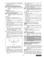
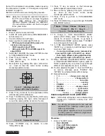
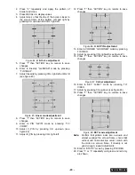
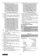
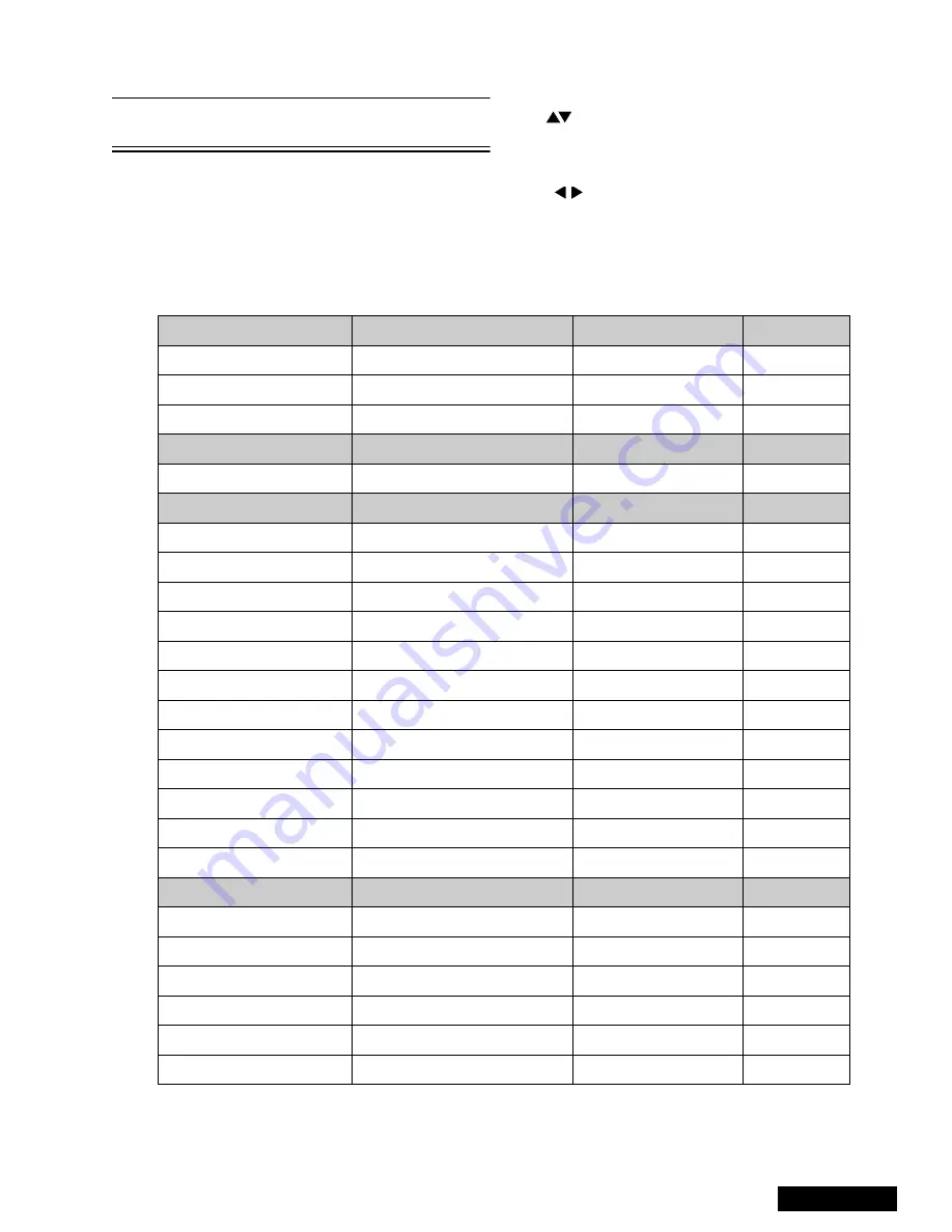
1080i Service mode (electronic controls, continued)

Note:

Registers marked as FIXED are factory preset,
the default value must not be changed

Important note:

Write down the original values (“b” in the
adjustment mode details, figure 60) for each
address adjustment before modifying values.

Follow the procedure below to access the various
service adjustments. (Same procedures applies to
each section.)

a.

Press

CH

buttons on the remote control to select any of

the seven service sub adjustment addresses. (“a” in
figure 60)

b. Press

The

buttons on the remote control to adjust the

level of the selected service adjustments.

MTS Adjustments

Description

Default Level

New Level

MTSIN

INPUT LEVEL

N/A

SEPAL

LOW LEVEL SEPARATION

N/A

SEPAH

HIGH LEVEL SEPARATION

N/A

CLOCK Adjustments

Description

Default Level

New Level

CLOCK

CLOCK

N/A

VIDEO Adjustments

Description

Default Level

New Level

COLOR

COLOR

1C

TINT

TINT

80

BRIGHT

SUB-BRIGHTNESS

02 00

CONT

SUB-CONTRAST

89

B-Y_G

MAGENTA TINT ADJ

40

R-Y_A

YELLOW TINT ADJ

80

CUT R

RED CUT-OFF

01 FB

CUT B

BLUE CUT-OFF

01 EC

R DR

RED DRIVE

57

B DR

BLUE DRIVE

70

I ABL

ABL

00

C_OFF

COLOR ADJ. CUT-OFF

00

HDEF Adjustments

Description

Default Level

New Level

H POS

HORIZONTAL POSITIONING

00 C2

H WID

HORIZONTAL WIDTH

2B

PCC

PINCUSHION CORRECTION

0C

EWCOR

CORNER CORRECTION

03

EWTRA

TRAPEZOID

08

HCORR

HORIZONTAL CORRECTION

0E

Summary of Contents for PT47WX52F - 47" PROJECTION TV HD

Page 1: ...ienced repair technicians only and is not designed for use by the general public It does not contain warnings or cautions to advise non technical individuals of potential dangers in attempting to service a product Products powered by electricity should be serviced or repaired only by experienced professional technicians Any attempt to service or repair the product or products dealt with in this Se...

Page 2: ... removed or when checking the cleanliness of the lens 3 Do not remove the lens or metal box to check the projection tube for operation by watching it directly Use a mirror or paper to view the image Before returning a serviced PTV to the owner the service technician must thoroughly test the unit to ensure that is completely safe to operate Do not use a line isolation transformer when testing Leaka...

Page 3: ...r Typically the melting point is 50 70 F 30 40 C higher Please use a high temperature soldering iron and set it to 700 20 F 370 10 C Pb free solder will tend to splash when heated too high about 1100 F or 600 C If you must use Pb solder please completely remove all of the Pb free solder on the pins or solder area before applying Pb solder If this is not practical be sure to heat the Pb free solder...

Page 4: ... 4 Figure 3 Measuring H V 4 Connect a H V meter static type class 0 1 with high voltage leads to high voltage distributor on FBT See figure 4 Figure 4 DVM power supply connection 5 Connect the 15 25 V DC variable power supply to TPD8 or IC802 pin 2 D Board and heat sink of Q551 see figure 4 Procedures 1 Apply a NTSC white pattern 2 Turn PTV ON 3 Adjust the picture or brightness controls so that th...

Page 5: ...X 4 3 Widescreen 16 9 and non widescreen 4 3 PTVs use the same light box for this reason is important to set it to the correct version 16 9 or 4 3 To change the format please refer to figure 62 on page 43 Be sure to select the correct format for the serviced PTV ...

Page 6: ...0i Vertical size adjustment VSIZE 25 NTSC ZOOM Vertical size adjustment VSIZE 26 NTSC Horizontal phase adjustment H POS 26 HD 1080i Horizontal phase adjustment H POS 26 Trapezoid adjustment EWTRA 26 NTSC Pincushion adjustment PCC 26 HD 1080i Pincushion adjustment PCC 27 Centering magnets adjustment 27 NTSC Horizontal size adjustment H WID 27 HD 1080i Horizontal size adjustment H WID 27 Convergence...

Page 7: ...until solder flows Do not apply heat for more than 3 seconds How to replace Flat IC Required tools 1 Cut the pins of the defective IC with the wire cutter pliers and remove it completely away from the board If the IC is glued to the board apply hot air to complete the removal CAUTION Do not pull or twist the pliers it may damage the soldering pads in the board 2 Using the soldering Iron and the lo...

Page 8: ... or incorrect voltages will be measured WARNING This PTV has been designed to meet or exceed applicable safety and x ray radiation protection as specified by government agencies and independent testing laboratories To maintain original product safety design standards relative to X ray radiation and shock and fire hazard parts indicated with the symbol on the schematic must be replaced with identic...

Page 9: ... RATE 1080i 480p NTSC LINE DOUBLER 480p SMOOTH PROGRESSIVE MTS SAP DBX X Bass Bl Treb control X AI sound X SURROUND X Spatializer BBE BBE Built in audio power 15WX2 10 10WX2 10 Number of speakers 4 2 A V in rear front 4 3 1 S VHS in rear front 2 1 Audio out Fixed Variable COMPONENT INPUT Y Pb Pr 2 Dimensions mm WxDxH in 1111x1236x626 43 74x48 66x24 64 Weight kg lbs 82 180 78 Power source V Hz 120V...

Page 10: ... K Board TNP2AA089 front button panel R Board TNPA0615AB IR receiver Table 2 Boards designation Note The A Board TNP2AH035 is non serviceable Except for A Board both tuners IC2302 IC7001 IC7002 IC871 IC872 IC873 If any of these components or board is defective repleace it with a new one and take back the defective board to the service center Notice When ordering any board add and S after the board...

Page 11: ...rating features when menus are displayed Channel Press to select programmed channels Press to highlight desired features when menus are displayed Also use to select cable converter box channels after programming remote control infra red codes the TV AUX CABLE switch must be set in CABLE position Action Press to display main menu and access on screen feature and adjustment menus TV Video Press to s...

Page 12: ...on Press to switch to the previous channel ACTION Button Press to display main menu and access or exit on screen features and adjustment menus REW PLAY FF TV VCR STOP PAUSE REC VCR CHANNEL Buttons Component function buttons DBS EXIT DBS GUIDE Buttons DBS function buttons LIGHT Button Press to light remote control buttons SAP Access second audio program ASPECT Select picture size ratio to match pro...

Page 13: ...on Press to switch to the previous channel ACTION button Press to display Main Menu and access or exit On Screen features and Adjustment Menus REW PLAY FF TV VCR STOP PAUSE REC VCR CHANNEL buttons Component function buttons DBS EXIT DBS GUIDE buttons DBS function buttons LIGHT button Press to light remote control buttons SAP Access second audio program ASPECT Select picture size ratio to match pro...

Page 14: ...s located in specific areas depending on how many times the LED is flashing this will tell you what circuit should be checked Make a count of flashing and see Table 3 Please use this feature effectively especially for intermittent problems Table 3 SOS of front LED After the count Proceed to check that area verify what board is the problem located this way the area to check will be reduced until th...

Page 15: ...GV RH GH BH SUB Y MAIN Y VIDEO OUTPUT SUB TUNER VIDEO OUTPUT 0 26V 0 46V 8 96V 2 58V 9 47V 3 6V 3 58V 3 45V 3 11V 3 17V 0 00V 0 24V 3 83V 4 46V 20 97V 23 77V 0 26V 0 14V 0 00V 0 47V 0 53V 3 27V 6 96V 3 52V 2 13V 2 25V 5 24V 3 77V 4 46V 0 00V G 3 19V 0 46V Note All the measurments are in DC with a digital multimeter color bar pattern picture settings normalized and sound set to minimum ...

Page 16: ...10µs sec div Sub Y 15 72kHz 1 92Vpp 10µs sec div NTSC video 15 72kHz 2 02Vpp 10µs sec div VP 60Hz 3 36Vpp 5µs sec div HP 31 65kHz 3 32Vpp 10µs sec div Conv 18 60 24Hz 0 75Vpp 5µs sec div Conv 18 60 24Hz 0 24Vpp 5µs sec div G 31 65kHz 4 72Vpp 10µs sec div R 31 65kHz 4 44Vpp 10µs sec div B 31 65kHz 4 40Vpp 10µs sec div Note Waveforms were obtained with colorbar pattern picture settings normalized an...

Page 17: ...10 Chassis boards layout Board description A Main chassis video processing convergence audio processing D Power supply vertical out horizontal out LB Blue CRT output LG Green CRT output LR Red CRT output R IR sensor A D LR LB LG R Top view Back view ...

Page 18: ...igure 11 2 Each speaker is secured to the cabinet with 4 screws 3 Disconnect the R L speaker lead connectors from the speaker units Cabinet back lower cover removal figure 12 1 Remove 7 hex screws around the perimeter marked with arrows See figure 12 for screws location 2 Remove 3 screws from around the A V terminal board marked with arrows Figure 12 Lower cabinet back removal Cabinet back cover r...

Page 19: ...een The orientation and order of the screens is critical for displaying pictures properly Detailed screen assembly can be seen in figure 14 Main chassis block figure 15 1 Remove the speaker grille See figure 11 2 Remove the cabinet back lower cover See figure 12 3 The main chassis block is secured to the cabinet by screws at front behind the Speaker Grill and inside on the bottom of the optical fr...

Page 20: ...from the defective CRT neck 7 Remove 2 screws from the defective CRT housing See figure 19 CAUTION Do not remove the 4 CRT lens screws Figure 19 CRT replacement CAUTION Support the CRT assembly when loosening screws 8 Release CRT anode lead from CRT chassis wire clamp and all other wires from holders 9 Loosen a screw that secures the DY and remove it from the CRT neck Caution To insure x ray radia...

Page 21: ...he same location as on other CRT focus lens Figure 22 CRT screw tightening order Note Please assemble with screws in the order shown and tighten with the same torque Optical block position adjustment Figure 23 Optical block position The optical block mounting has holes to allow for the different size projection screens These mounts will adjust to projection screens If the optical block is removed ...

Page 22: ... voltmeter to each test point and confirm the B voltages see Table 4 FRONT REAR Protective screen Fresnel screen Lenticular screen Front cabinet note vertical ridges note circular ridges Label on lower left corner rear side Label on lower left corner front side Labels on opposite sides No Test point D Board Voltage 1 TPD14 138 6 1 0 2 TPD13 19 0 1 5 3 TPD12 19 0 1 5 4 TPD11 19 0 1 5 5 TPD10 22 0 1...

Page 23: ...on remote to display DACs menu then select DAC by pressing CH RIGHT LEFT and VOL UP DOWN then press ACTION to enter to DAC then adjust by pressing VOL RIGHT LEFT press ACTION to save press ACTION again or OTHER to exit without saving Procedure Note 1080i 480p 480i pattern can be obtained from Panasonic s TU DST51 set top box DTV decoder 1 Enter to service mode and set the following default DATA No...

Page 24: ...ame for the red focus lens while projecting red only 6 Repeat for blue Electric VM focus adjustment complete adjustment Perform this adjustment when a CRT is replaced or when major adjustment is required Preparation 1 Apply a NTSC crosshatch pattern with dots 2 Set CONV MUTE DAC from 0 to 1 disabling digital convergence 3 Position the longer tab of the four pole magnet to 90 degrees uncorrected po...

Page 25: ...F DAC from 00 to 01 to project green only 17 Repeat above procedures for the green 18 Set VIDEO C_OFF DAC from 00 to 02 to project red only 19 Repeat above procedures for the blue 20 Enable digital convergence by changing DAC MUTE from 01 to 00 21 Following adjustments paint position of DY centering magnets and fix the centering magnets of DY dummy rings of VM coil four pole magnets of VM coil and...

Page 26: ... C_OFF DAC from 01 to 00 HD 1080i Horizontal phase adjustment H POS Note 1080i 480p 480i pattern can be obtained from Panasonic s TU DST51 set top box DTV decoder 1 Apply a HD 1080i pattern 2 Repeat NTSC horizontal phase adjustment from step 2 Trapezoid adjustment EWTRA 1 Set default value NTSC Pincushion adjustment PCC Note 1080i 480p 480i pattern can be obtained from Panasonic s TU DST51 set top...

Page 27: ...nce by changing DAC MUTE from 01 to 00 13 Set VIDEO C_OFF DAC from 02 to 00 Following the adjustment make sure that all deflection coils are pushed completely toward the CRT cones and that all screws are tightened NTSC Horizontal size adjustment H WID Note 1080i 480p 480i pattern can be obtained from Panasonic s TU DST51 set top box DTV decoder This adjustment is intended to adjust horizontal size...

Page 28: ...monoscope pattern center 15 Press 0 key to go back to CONVERGENCE ADJ mode 16 Press TV VIDEO key to cycle through COARSE ADJ MODE options 17 To change to FINE ADJUSTMENT MODE options DAC FINE press TV VIDEO key on remote for at least 3 seconds to go back to COARSE ADJ MODE options press TV VIDEO on remote again for 3 seconds 18 In FINE ADJUSTMENT MODE options press MUTE key on remote to switch bet...

Page 29: ...n see figure 46 11 Adjust H_PIN by pressing VOL right left 12 Press 7 then ACTION key on remote to save changes Figure 46 H V PIN adjustment 13 Enter to CORNER G CORNER mode by pressing TV VIDEO 14 Adjust by pressing VOL right left see figure 47 15 Press 7 then ACTION key on remote to save changes Figure 47 Corner adjustment 16 Enter to KEY G KEY mode by pressing TV VIDEO 17 Adjust by pressing CH ...

Page 30: ...pattern are displayed 38 Adjust B STATIC so that the center of blue overlaps with the center of green see figure 51 Figure 51 B STATIC adjustment 39 Perform all adjustments for blue B SKEW B LINEAR B SIZE B PIN B CORNER B KEY 40 Display border and cross pattern and confirm that blue overlaps with green pattern if it is not satisfactory repeat for blue 41 Press 1 or 3 key repeatedly on remote until...

Page 31: ...cursor to any of the 9 positions for EASY mode see figure 52 11 This adjustment may help to make rounded lines become straight lines 12 Adjust to make lines as straight as possible 13 Enter to POINT G POINT for green mode by pressing TV VIDEO 14 POINT mode allows to move line horizontally and vertically from the perimeter of cursor making rounded lines become straight see figure 54 15 In POINT mod...

Page 32: ...ed and green 31 Press 1 or 3 key on remote to display red green and blue white 32 At this point the crosshatch pattern should look white 33 If the crosshatch pattern is not only white repeat adjustment for that color red or blue 34 Once the crosshatch pattern looks only white perform the adjustments for White POINT ORIG POINT LINE notice that each adjustment is only for white red green blue 35 Adj...

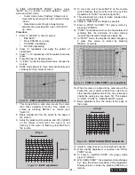
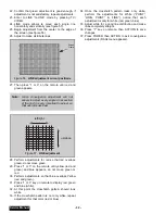
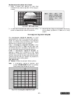
Page 33: ...alignment template to the viewing screen of the PTV Make sure the center lines are properly aligned If a template is not available one can be created by following the instructions below Create a convergence alignment template by drawing a pattern as in figure 59 in the actual dimensions on transparent film or tracing paper Start with the Horizontal and Vertical Center Axis and work outwards until ...

Page 34: ... needed to apply the format For some adjustments is required to perform adjustment for each format convergence adjustment must be perform for 480i p same for interlace progressive 1080i and ZOOM 480i A 1080i 480p 480i pattern can be obtained from Panasonic s TU DST51 set top box DTV decoder Exiting the service mode This PTV goes out from service mode when it is unpluged or turned OFF To exit the s...

Page 35: ...A TINT ADJ X N A X R Y_A YELLOW TINT ADJ X N A X CUT R RED CUT OFF X N A X CUT B BLUE CUT OFF X N A X R DR RED DRIVE X N A X B DR BLUE DRIVE X N A X I ABL ABL X X X C_OFF COLOR ADJ CUT OFF X X X HDEF H POS HORIZONTAL POSITIONING X N A X HWID HORIZONTAL WIDTH X N A X PCC PINCUSHION CORRECTION X N A X EWCOR CORNER CORRECTION X N A X EWTRA TRAPEZOID X N A X HCORR HORIZONTAL CORRECTION X N A X VDEF VS...

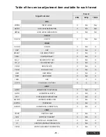
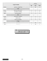
Page 36: ...RS COARSE ADJUSTMENT X X X FINE FINE ADJUSTMENT X X X DAF H PAR HORIZONTAL PARABOLA X X X V SAW VERTICAL SAW X X X V PAR VERTICAL PARABOLA X X X OTHER ACL X N A X HHS X N A X Signal Formated Format 480i 480p 1080i Note PTV detects automatically the format of the input signal 480i 480p or 1080i ...

Page 37: ...level of the selected service adjustments MTS Adjustments Description Default Level New Level MTSIN INPUT LEVEL 21 SEPAL LOW LEVEL SEPARATION 06 SEPAH HIGH LEVEL SEPARATION 1A CLOCK Adjustments Description Default Level New Level CLOCK CLOCK 128 VIDEO Adjustments Description Default Level New Level COLOR COLOR 13 TINT TINT 80 BRIGHT SUB BRIGHTNESS 01 DB CONT SUB CONTRAST 89 B Y_G MAGENTA TINT ADJ ...

Page 38: ...L SIZE 00 VLIN VERTICAL LINEARITY 10 V S VERTICAL S CORRECTION 0A V I VERTICAL ENDING CORRECTION 0F DEFAULT VSYM VERTICAL MAGNET CORRECTION 04 DEFAULT VCORR VERTICAL CORRECTION 0C CONV Adjustments Description Default Level New Level MUTE DIGITAL CONV ON OFF 00 COARS COARSE ADJUSTMENT ADJUSTMENT FINE FINE ADJUSTMENT ADJUSTMENT DAF Adjustments Description Default Level New Level H PAR HORIZONTAL PAR...

Page 39: ...l of the selected service adjustments MTS Adjustments Description Default Level New Level MTSIN INPUT LEVEL N A SEPAL LOW LEVEL SEPARATION N A SEPAH HIGH LEVEL SEPARATION N A CLOCK Adjustments Description Default Level New Level CLOCK CLOCK N A VIDEO Adjustments Description Default Level New Level COLOR COLOR N A TINT TINT N A BRIGHT SUB BRIGHTNESS N A CONT SUB CONTRAST N A B Y_G MAGENTA TINT ADJ ...

Page 40: ...RTICAL SIZE N A VLIN VERTICAL LINEARITY N A V S VERTICAL S CORRECTION N A V I VERTICAL ENDING CORRECTION N A VSYM VERTICAL MAGNET CORRECTION N A VCORR VERTICAL CORRECTION N A CONV Adjustments Description Default Level New Level MUTE DIGITAL CONV ON OFF 00 COARS COARSE ADJUSTMENT ADJUSTMENT FINE FINE ADJUSTMENT ADJUSTMENT DAF Adjustments Description Default Level New Level H PAR HORIZONTAL PARABOLA...

Page 41: ...e level of the selected service adjustments MTS Adjustments Description Default Level New Level MTSIN INPUT LEVEL N A SEPAL LOW LEVEL SEPARATION N A SEPAH HIGH LEVEL SEPARATION N A CLOCK Adjustments Description Default Level New Level CLOCK CLOCK N A VIDEO Adjustments Description Default Level New Level COLOR COLOR 1C TINT TINT 80 BRIGHT SUB BRIGHTNESS 02 00 CONT SUB CONTRAST 89 B Y_G MAGENTA TINT...

Page 42: ...L SIZE 40 VLIN VERTICAL LINEARITY 15 V S VERTICAL S CORRECTION 19 V I VERTICAL ENDING CORRECTION 0F DEFAULT VSYM VERTICAL MAGNET CORRECTION 04 DEFAULT VCORR VERTICAL CORRECTION 0C CONV Adjustments Description Default Level New Level MUTE DIGITAL CONV ON OFF 00 COARS COARSE ADJUSTMENT ADJUSTMENT FINE FINE ADJUSTMENT ADJUSTMENT DAF Adjustments Description Default Level New Level H PAR HORIZONTAL PAR...

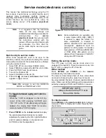
Page 43: ...ode To exit service mode just unplug PTV from AC line or turn it OFF or press ACTION and POWER on the receiver simultaneously for at least 2 seconds Press POWER on remote to display DACs ON REMOTE MUTE Hold pressed MUTE on remote for at least 5 seconds to display eeprom addresses ON REMOTE ACTION VOL Once in eeprom addresses press CH up down until 0010 xxxx is displayed ON REMOTE CH ON REMOTE CH I...

Page 44: ...OTE A ON REMOTE ACTION To view the adjustments menu press POWER on remote Once in adjustments menu press VOL right left and CH up down on remote to select adjustment Press ACTIONon remote to enter the adjustment AGING MODE Press VOL UP and ACTION simultaneously on PTV Yellow CHK appears in upper left corner of screen Volume Up Down operate rapidly Customer Controls are set to nominal level IMPORTA...

Page 45: ...ext adjustment ON REMOTE TO to make adjustment CH CH VOL VOL Press POWER or ACTION on remote to exit the adjustment EXIT POWER ON REMOTE IMPORTANT NOTE Always verify that PTV is out from service mode To exit service mode just unplug PTV from AC line or turn it OFF or press ACTION and POWER on the receiver simultaneously for at least 2 seconds ...

Page 46: ...x DTV decoder This adjustment requires that the servicer use its skills in observing what a colorbar pattern should looks like Preparation 1 Set the following in the user picture menu as follows PIC MODE VIVID COLOR center 31 PICTURE max 63 BRIGHT center 31 SHARPNESS min 0 TINT 31 NATURAL COLOR OFF COLOR TEMPERATURE NORMAL Procedure 1 Apply a NTSC color bar pattern 2 Adjust DAC TINT so that the fo...

Page 47: ... is composed of two colors blue and red 4 Check to see that magenta does not have too much blue or too much red 5 Check cyan Cyan is composed of blue and green It should not have too much blue or green 6 Use a test signal from a VCR or laser disk that has a pre recorded close up of a signal that has good flesh tones 7 The signal on the VCR or laser disk should look normal Color check Using a clean...

Page 48: ...reparation Connect the frequency counter from IC001 MPU Pin 10 or TPA009 to cold ground Note Frequency Counter probe capacitance should be 8pF or less Procedure 1 Turn the PTV ON with the AC power applied 2 Measure TPA009 IC001 MPU pin 10 for frequency and record the reading Note Pin 10 measurement must have at least four digits of resolution following the decimal point Example 000 0000 3 Place th...

Page 49: ...gram Figure 65 Audio signal path block diagram A Board Tuner 1 A1 AYUV1 AYUV2 A PROG OUT IC3001 AUDIO INPUT SELECTOR A2 A3 A4 IC2451 AUDIO CONTROL IC2304 VAO IC2302 L R AMP IC1002 MPU MUTE Qs AUDIO OUT CONNECTORS R L IC2201 MTS Audio MUTE VAO MUTE ...

Page 50: ...NPUT SELECTOR V2 VIDEO PROG OUT V3 V4 LR BOARD BLUE PRT GREEN PRT RED PRT MAIN Y Pb Pr SUB Y Pb Pr OSD RGB OSD CONVERGENCE VM VM VM VM R G B R G B R G B OSD MAIN SUB CC Y UV Y UV Y UV SV2 IC4018 IC4025 SGRAM 16M IC4007 FIFO MEM 5 IC4006 IC4011 IC3002 VIDEO A D 10BIT INPUT SELECTOR IC7110 IC4015 IC4019 IC7107 IC1002 MPU R B LG BOARD LB BOARD SIGNAL PROCESSOR OSD SWITCH ...

Page 51: ... SDA2 RM IN SCL2 GND SCL1 7V FA SDA1 IC2451 AUDIO PROCESSING IC601 VERTICAL DRIVE IC602 VERTICAL DEFLECTION CORRECTION IC2201 MTS IC7107 CONVERGENCE PROCESSOR TUNER1 MAIN IC1004 EEPROM TUNER2 SUB IC3001 A V SELECTOR IC3002 V SELECTOR IIC1 IIC2 IC4018 SIGNAL PROCESSING SLAVE IC4011 SIGNAL PROCESSING MASTER ...

Page 52: ... 3 4 5 6 7 8 9 10 11 12 13 14 15 16 GND 20V GND 20V GND 20V GND 20V GND GND GND GND ABL GND SOS GND D1 A1 1 2 3 4 5 6 7 8 9 10 11 12 13 14 15 16 20V GND SOUND 20V GND SOUND 20V GND SOUND 20V C BTL 40V AC ON OFF P_BTL 40V STAND BY GND STBY 7V NC NC TUNER GND TUNER GND R1 A51 1 2 3 STB 3 3V RM IN GND K3 A8 1 2 3 4 5 6 GND KEY SCAN 1 KEY SCAN 2 TP GND LED LR1 LG3 1 2 3 4 5 6 7 8 9 10 11 12 13 14 210V...

Page 53: ...iption of connectors continued LG2 D5 1 2 3 4 5 6 7 8 9 10 210V NC GND GND 18V 12V HEATER GND NC 40V B OF VM A9 EEPROM 1 2 3 4 5 6 7 NC WP GND SCL SDA NC NC A10 BUSSCON 1 2 3 4 5 6 7 8 STBY 7V FA GND SCL1 SDA1 SCL2 SDA2 RM IN ...

Page 54: ... C 01UF K 50V C418 ECQB1H183JF3 CAP P 018UF J 50V C421 ECEA1CN220UB CAP E 22UF 16V C461 F2A1H221A162 CAP E 220UF 50V C501 F2A1V101A127 CAP E 100UF 35V C502 ECQV1H105JL3 CAP P 1 0UF J 50V C503 ECKR2H102KB5 CAP C 1000PF K 500V C509 ECWF2474JSR CAP P 47UF J 200V C511 ECWH20222JVY CAP P 2200PF J 2KV C512 ECWH20102JVY CAP P 1000PF J 2KV C513 ECQF4103JZH CAP P 01UF J 400V C514 ECWH20222JVY CAP P 2200PF ...

Page 55: ...5 CAP C 022UF Z 50V C851 ECQV1H104JL3 CAP P 10UF J 50V C852 F2A1V101A127 CAP E 100UF 35V C854 F2A1C221A159 CAP E 220UF 16V C855 TCJ2VB1E104K CAP C 1UF K 25V C883 ECQV1H474JL3 CAP P 47UF J 50V C890 TCJ2VF1H103Z CAP C 01UF Z 50V C897 ECQV1H474JL3 CAP P 47UF J 50V C898 TCJ2VF1H103Z CAP C 01UF Z 50V C902 ECQM2103KZ3 CAP P 01UF K 200V REF NO PART NO DESCRIPTION C903 ECKR1H103ZF5 CAP C 01UF Z 50V C904 E...

Page 56: ...DIODE ZENER D659 MA4110MTA DIODE ZENER D660 MA4110MTA DIODE ZENER D662 MA4110MTA DIODE ZENER D663 MA4110MTA DIODE ZENER D702 D1NL40V70 DIODE D801 RBV 408 BRIDGE RECTIFIER D802 ERZC10VK361G VARISTOR D815 MA165TA5VT DIODE SWITCHING REF NO PART NO DESCRIPTION D816 MA700TA DIODE D817 AU01ZV0 DIODE D818 MA3270LTX DIODE D819 TMPG10G3 DIODE D822 ERA22 02V3 DIODE D825 FMLG16SLF116 DIODE D827 RL4ZLF J6 DIO...

Page 57: ...26 TALL08T330KA LINE FILTER L827 TALL08T330KA LINE FILTER L888 TALL08T680KA LINE FILTER L901 EXCELSA35T FERRITE BEAD L902 EXCELSA35T FERRITE BEAD L903 EXCELSA35T FERRITE BEAD L933 EXCELSA35T FERRITE BEAD L934 EXCELSA35T FERRITE BEAD L935 EXCELSA35T FERRITE BEAD L961 EXCELSA35T FERRITE BEAD REF NO PART NO DESCRIPTION L962 EXCELSA35T FERRITE BEAD L963 EXCELSA35T FERRITE BEAD TRANSISTORS Q301 2SC1473...

Page 58: ...T RES C 18K J 1 4W R311 ERDS2TJ470T RES C 47 J 1 4W R312 ERG7ZJ272 RES M 2 7K J 7W R315 ERDS2TJ563T RES C 56K J 1 4W REF NO PART NO DESCRIPTION R316 ERDS2TJ821T RES C 820 J 1 4W R319 ERG12SJ101P RES M 100 J 1W R320 ERDS1FJ330P RES C 33 J 1 2W R321 ERDS1FJ330P RES C 33 J 1 2W R322 ERG12SJ101P RES M 100 J 1W R325 ERDS2TJ473T RES C 47K J 1 4W R327 ERC12GK331D RES C 330 K 1 2W R328 ERDS1TJ104T RES C 1...

Page 59: ...J6GEYJ103V RES M 10K J 1 10W R539 ERDS2TJ393T RES C 39K J 1 4W R541 ERDS2TJ563T RES C 56K J 1 4W R550 ERDS2TJ273T RES C 27K J 1 4W R601 ERJ6GEYJ101V RES M 100 J 1 10W R602 ERJ6GEYJ101V RES M 100 J 1 10W REF NO PART NO DESCRIPTION R603 ERJ6GEYJ562V RES M 5 6K J 1 10W R604 ERJ6GEYJ101V RES M 100 J 1 10W R605 ERJ6GEYJ101V RES M 100 J 1 10W R606 ERJ6GEYJ101V RES M 100 J 1 10W R607 ER0S2THF6201 RES M 6...

Page 60: ...M 220 J 3W R912 ERDS2TJ681T RES C 680 J 1 4W R913 ERDS1FVJ152T RES C 1 5K J 1 2W R914 ERDS1FVJ152T RES C 1 5K J 1 2W R915 ERQ14AJ220P RES F 22 J 1 4W R916 ERQ14AJ220P RES F 22 J 1 4W R917 ERQ14AJ100P RES F 10 J 1 4W REF NO PART NO DESCRIPTION R925 ERDS2TJ221T RES C 220 J 1 4W R926 ERDS2TJ221T RES C 220 J 1 4W R928 ERQ14AJ220P RES F 22 J 1 4W R929 ERDS2TJ101T RES C 100 J 1 4W R942 ERDS1FVJ152T RES ...

Page 61: ...005 TJSC00700 CRT SOCKET DY KDY2ASC29F YOKE DEFLECTION M006 TXF3A01ECV ASSY DAG GND M007 TKG2AF020 A B LENS M008 TKG2AA50091 MIRROR GLASS M009 TKG2AD00071 SCREEN PANEL PROTECTIVE PT 47WX52F CF M010 TKG2AH50471 SCREEN FRESNEL M011 TKG2AH50461 SCREEN LENTICULAR M012 TXFLB01FSER ASSY ADJUSTED LIGHT BOX M013 TMK2AX00305 SHEET LIGHT COVER REF NO PART NO DESCRIPTION M014 TNXB003 FOCUS BLOCK M015 TKU2AC2...

Page 62: ...4 CAP P 068UF K 50V RESISTOR TYPE TOLERANCE C Carbon F 1 F Fuse J 5 M Metal Oxide K 10 S Solid M 20 W Wire Wound G 2 CAPACITOR TYPE TOLERANCE C Ceramic C 0 25pF E Electrolytic D 0 5pF P Polyester F 1pF S Styrol J 5 T Tantalum K 10 L 15 M 20 P 10 0 Z 80 20 ...

Page 63: ... may vary depending on the type of Oscilloscope used and its settings 5 Ground symbol shown on waveform number indicates Hot ground lead connection of the Oscilloscope CAUTION Incorrect ground connection of the test equipment will result in erroneous readings 3 VOLTAGE MEASUREMENTS 1 Voltage measurement AC input to the Receiver is 120V NTSC HD 1125i 525P when applicable signal generator is connect...

Page 64: ... de la señal y el contenido de la imagen Las fuentes de voltajes son nominales 2 El símbolo indica el tipo de tierra que se utiliza en la conexión del medidor PRECAUCION SI no se utiliza la conexión a la tierra adecuada se obtendrán mediciones equivocadas y podría dañar el equipo de medición MEDICIÓN DE FORMAS DE ONDA 1 Un símbolo como indica el punto para medir una señal La medición puede hacerse...

Page 65: ... 65 Notes PARTS LIST ...

Page 66: ... 66 D Board Schematic ...

Page 67: ... 67 D Board Schematic ...

Page 68: ... 68 D Board Schematic ...

Page 69: ... 69 Jumper between pin 7 and pin 1 D Board Schematic ...

Page 70: ... 70 D Board Schematic ...

Page 71: ... 71 D Board Schematic ...

Page 72: ... 47 4 43 N C GND 4 86 3 86 6 02 3 19 IC803 1 2 3 16 01 12 01 GND IC805 1 2 3 19 04 GND 9 06 IC811 1 2 19 04 18 03 Q406 6 09 0 06 0 00 B C E Q501 0 00 16 07 3 09 Q502 0 00 0 01 8 44 Q603 0 62 6 08 0 00 B C E Q604 6 07 9 06 5 49 Q503 0 28 8 46 0 00 D BOARD TRANSISTORS TNPH0371 Q509 29 39 138 80 31 83 Q510 31 82 138 80 31 32 Q551 0 07 4 53 0 21 Q601 0 60 2 76 0 00 Q602 4 11 9 06 3 53 Q605 4 13 0 00 4...

Page 73: ... 73 NOTES NOTES ...

Page 74: ... 74 D Board Layout ...

Page 75: ... 75 D Board Layout ...

Page 76: ... 76 A Board Schematic ...

Page 77: ... 77 A Board Schematic ...

Page 78: ... 78 A Board Schematic ...

Page 79: ... 79 A Board Schematic ...

Page 80: ... 80 A Board Schematic ...

Page 81: ... 81 A Board Schematic ...

Page 82: ... 82 A Board Schematic ...

Page 83: ... 83 A Board Schematic ...

Page 84: ... 84 Board section Top A Board Layout Top left portion ...

Page 85: ... 85 Board section Top A Board Layout Top right portion ...

Page 86: ... 86 Board section Top A Board Layout Bottom left portion ...

Page 87: ... 87 Board section Top A Board Layout Bottom right portion ...

Page 88: ... 88 Board section Bottom side A Board Layout Top left portion ...

Page 89: ... 89 Board section Bottom A Board Layout Top right portion ...

Page 90: ... 90 Board section Bottom A Board Layout Bottom left portion ...

Page 91: ... 91 Board section Bottom A Board Layout Bottom right portion ...

Page 92: ... 92 LG Board schematic TNP2AA112 LG Board schematic ...

Page 93: ...40 Q955 129 50 71 80 130 10 Q374 172 90 218 60 172 40 Q941 0 98 9 12 0 38 Q375 171 50 0 43 172 10 Q951 9 67 18 91 9 07 Q934 9 08 0 00 9 68 Q952 9 65 18 91 9 09 LG Board TNP2AA112 B C E Q935 9 08 18 91 8 49 Q936 9 68 18 91 9 11 LG Board layout TNP2AA112 LG Board integrated circuit TNP2AA112 IC880 1 2 3 18 91 GND 11 99 LG Board layout and voltages ...

Page 94: ... 94 LR Board schematic TNP2AA111 LR Board schematic ...

Page 95: ...97 9 12 0 37 Q958 9 69 71 30 9 12 Q303 0 60 0 08 0 00 Q905 9 10 8 90 8 49 Q353 11 98 173 70 11 65 Q906 9 72 18 91 9 13 Q354 174 90 218 60 174 60 Q907 8 49 6 00 9 11 LR Board voltages TNP2AA111 B C E Q355 173 70 0 42 174 20 Q901 137 80 130 20 138 40 LR Board schematic TNP2AA111 LR Board layout and voltages ...

Page 96: ... 96 LB Board schematic TNP2AA110 LB Board schematic ...

Page 97: ...71 90 Q964 0 98 9 10 0 37 Q966 9 09 18 91 8 49 Q363 3 86 11 54 3 70 Q395 170 60 0 42 171 50 Q967 9 72 18 91 9 14 Q364 3 92 0 00 3 51 Q959 129 30 71 40 129 90 Q968 8 50 0 00 9 11 Q365 5 91 11 98 5 28 Q960 9 67 71 50 9 10 LB Board voltages TNP2AA110 B C E Q366 5 08 11 98 4 48 Q368 4 48 0 00 3 96 LB Board layout TNP2AA110 LB Board layout and voltages ...

Page 98: ... 98 K Board schematic TNP2AA089 K Board layout TNP2AA089 K Board schematic and layout ...

Page 99: ... 99 G Board schematic TNP2AA090 G Board layout TNP2AA090 G Board schematic and layout ...

Page 100: ...4 47 4 43 N C GND 4 86 3 86 6 02 3 19 IC803 1 2 3 16 01 12 01 GND IC805 1 2 3 19 04 GND 9 06 IC811 1 2 19 04 18 03 Q406 6 09 0 06 0 00 B C E Q501 0 00 16 07 3 09 Q502 0 00 0 01 8 44 Q603 0 62 6 08 0 00 B C E Q604 6 07 9 06 5 49 Q503 0 28 8 46 0 00 D Board transistors voltages TNPH0371 Q509 29 39 138 80 31 83 Q510 31 82 138 80 31 32 Q551 0 07 4 53 0 21 Q601 0 60 2 76 0 00 Q602 4 11 9 06 3 53 Q605 4...

Page 101: ...7 19 72 0 36 0 37 0 23 0 23 19 71 0 28 IC2302 4 5 6 7 8 9 10 11 12 13 14 15 16 17 18 19 20 21 22 23 24 25 26 27 28 23 50 23 45 0 35 20 99 9 36 4 90 0 00 2 54 0 05 0 00 0 00 5 20 GND 22 09 0 00 5 31 0 06 0 00 0 00 N C 9 30 20 99 0 32 23 45 13 20 A Board integrated circuits voltages TNP2AH035 IC7001 1 2 3 4 5 6 7 8 9 GND GND 18 60 19 70 18 84 0 40 0 39 19 70 0 53 10 11 12 13 14 15 16 17 18 18 84 0 0...

Page 102: ...Vp p A15 PIN 4 RED OUT 2 6 32 Vp p A15 PIN 6 GREEN OUT 3 2 74 Vp p A15 PIN 9 VM OUT 4 1 70 Vp p A15 PIN 11 S ABL 5 0 14 Vp p A4 PIN 16 DFCUT 6 3 24 Vp p A3 PIN 15 7 0 17 Vp p A2 PIN 13 ABL 8 1 00 Vp p TNR001 VIDEO 10 A Board A Board waveforms ...

Page 103: ... 6 48 Vp p IC601 pin 10 fbp in 19 8 40 Vp p IC601 PIN 15 H DRIVE OUT 20 4 96 Vp p IC601 PIN 22 V PULSE OUT 21 0 53 Vp p IC602 PIN 1 EHT FB ADJ 22 1 70 Vp p IC602 PIN 4 EW FB 23 1 90 Vp p IC602 PIN 6 V FB 24 4 80 Vp p IC602 PIN 13 V IN 25 2 84 Vp p IC602 PIN 14 TC 26 2 04 Vp p IC602 PIN 15 RAMP 27 D Board 27 6 Vp p LG2 PIN 7 HEATER 12 LG Board D LG Board waveforms ...

Page 104: ...Printed in USA K02042127PL0429 ...

Reviews: