- 44 -
Service Manual
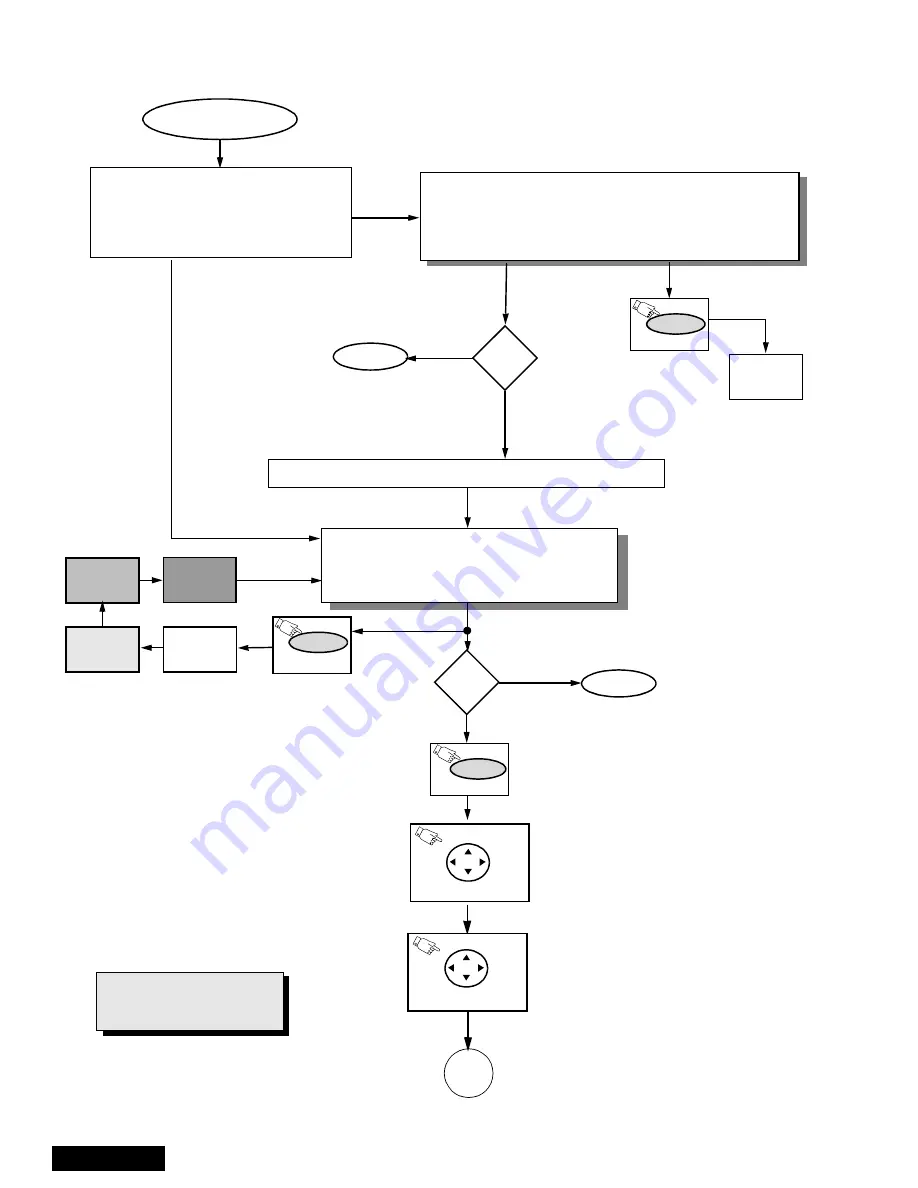
Instructional flow chart for service mode
Adj.
needed?
NORMAL MODE
Press Volume up simultaneously (ON receiver)
Adj.
needed?
WHITE
SCREEN
(ON REMOTE)
RECALL
WHITE
SCREEN
RED
SCREEN
GRN.
SCREEN
BLUE
SCREEN
POWER
(ON REMOTE)
SERVICE MODE
•
“CHK” turns red.
•
VOLUME up/down operate normally.
•
Customer controls are set to nominal level.
ENTRY TO SERVICE MODE
•
Select CABLE Mode.
•
Set SLEEP time for 30 Min.
•
Tune to Channel 124.
•
Adjust Volume to minimum.
•
Press VOL DOWN On Receiver.
EXIT
EXIT
Figure 63.Flow chart for service mode.
N
Y
N
Y
(ON REMOTE)
RECALL
(ON REMOTE)
A
(ON REMOTE)
ACTION
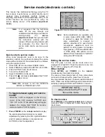
To view the adjustments
menu press POWER on
remote.
Once in adjustments menu press
VOL right/left and CH up/down on
remote to select adjustment.
Press ACTIONon remote to enter the
adjustment.
AGING MODE
•
Press VOL UP and ACTION simultaneously on PTV
•
Yellow “CHK” appears in upper left corner of screen.
•
Volume Up/Down operate rapidly.
•
Customer Controls are set to nominal level.
IMPORTANT NOTE:
Always verify that PTV is out
from service mode.
To exit service mode, just unplug PTV from AC
line or turn it OFF; or press ACTION and
POWER on the receiver simultaneously for at
least 2 seconds.
To exit service mode, just unplug PTV from AC
line o turn it OFF; or press ACTION and POWER
on the receiver simultaneously for at least 2
seconds.
ACTION
ACTION
Summary of Contents for PT47WX52F - 47" PROJECTION TV HD
Page 65: ... 65 Notes PARTS LIST ...
Page 66: ... 66 D Board Schematic ...
Page 67: ... 67 D Board Schematic ...
Page 68: ... 68 D Board Schematic ...
Page 69: ... 69 Jumper between pin 7 and pin 1 D Board Schematic ...
Page 70: ... 70 D Board Schematic ...
Page 71: ... 71 D Board Schematic ...
Page 73: ... 73 NOTES NOTES ...
Page 74: ... 74 D Board Layout ...
Page 75: ... 75 D Board Layout ...
Page 76: ... 76 A Board Schematic ...
Page 77: ... 77 A Board Schematic ...
Page 78: ... 78 A Board Schematic ...
Page 79: ... 79 A Board Schematic ...
Page 80: ... 80 A Board Schematic ...
Page 81: ... 81 A Board Schematic ...
Page 82: ... 82 A Board Schematic ...
Page 83: ... 83 A Board Schematic ...
Page 84: ... 84 Board section Top A Board Layout Top left portion ...
Page 85: ... 85 Board section Top A Board Layout Top right portion ...
Page 86: ... 86 Board section Top A Board Layout Bottom left portion ...
Page 87: ... 87 Board section Top A Board Layout Bottom right portion ...
Page 88: ... 88 Board section Bottom side A Board Layout Top left portion ...
Page 89: ... 89 Board section Bottom A Board Layout Top right portion ...
Page 90: ... 90 Board section Bottom A Board Layout Bottom left portion ...
Page 91: ... 91 Board section Bottom A Board Layout Bottom right portion ...
Page 92: ... 92 LG Board schematic TNP2AA112 LG Board schematic ...
Page 94: ... 94 LR Board schematic TNP2AA111 LR Board schematic ...
Page 96: ... 96 LB Board schematic TNP2AA110 LB Board schematic ...
Page 98: ... 98 K Board schematic TNP2AA089 K Board layout TNP2AA089 K Board schematic and layout ...
Page 99: ... 99 G Board schematic TNP2AA090 G Board layout TNP2AA090 G Board schematic and layout ...
Page 104: ...Printed in USA K02042127PL0429 ...

