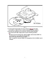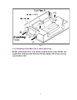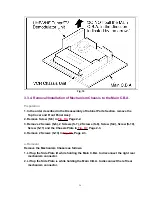
Cassette Tape firmly into the Cassette Up Ass'y with your left thumb.
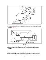
4. To install the Power Supply Ass'y to the Main C.B.A.:
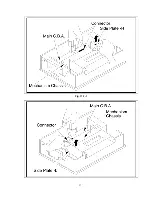
Connect connector P1001 and hook the tab of the Shield Case to the slot of the
Main C.B.A. as shown in
Fig. 2-2
.
Fig. 2-2
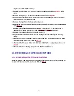
5. When lifting up the VCR Chassis Unit, do not pull up on the Top Plate of the
Cassette Up Ass'y.
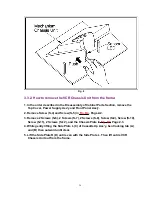
6. Model : D, E
When raising or opening the mechanism, place something insulated between the
Hi-Fi Audio/Video Head Amp Ass'y and Audio Jack.
Service Position (2)
Service position (2) is used to check the Mechanism and Electronic Circuits.
12
Summary of Contents for PV-4601 A
Page 14: ...Fig 2 3 14 ...
Page 27: ...Fig 11 1 1 27 ...
Page 40: ...Fig D1 40 ...
Page 42: ...Fig D2 42 ...
Page 43: ...Fig D3 43 ...
Page 44: ...Fig D4 44 ...
Page 45: ...Fig D5 45 ...
Page 46: ...Fig D7 46 ...
Page 47: ...Fig D8 47 ...
Page 51: ...Fig M2 1 Fig M2 2 51 ...
Page 53: ...Fig M4 1 53 ...
Page 77: ...Fig M19 77 ...
Page 84: ...Fig J5 84 ...
Page 85: ...Fig J6 85 ...
Page 87: ...Fig J9 87 ...
Page 88: ...Fig J10 88 ...
Page 89: ...Fig J11 89 ...
Page 90: ...Fig J12 90 ...
Page 91: ...Fig J13 91 ...
Page 92: ...Fig J15 92 ...
Page 93: ...93 ...
Page 96: ...96 ...
Page 102: ...with the holes on the Pinch Lift Cam as shown in Fig A6 102 ...
Page 103: ...103 ...
Page 105: ...Fig K1 105 ...
Page 106: ...Fig K2 106 ...
Page 107: ...Fig K3 107 ...
Page 109: ...Fig B1 109 ...
Page 114: ...Fig E1 4 3 2 HOW TO READ THE ADJUSTMENT PROCEDURES 114 ...
Page 115: ...Fig E2 115 ...
Page 134: ...R6004 ERJ6GEYJ333V MGF CHIP 1 10W 33K 134 ...
Page 136: ...R6085 ERJ6GEYJ223V MGF CHIP 1 10W 22K 136 ...
Page 140: ...C4601 ECEA1CKA100 ELECTROLYTIC 16V 10 140 ...
Page 147: ...R6065 ERJ6GEYJ223V MGF CHIP 1 10W 22K 147 ...
Page 167: ...9 11 Operation Block Diagrams 1 167 ...
Page 178: ......
Page 204: ......
Page 205: ......


