Multi Function Display
Index of Controls
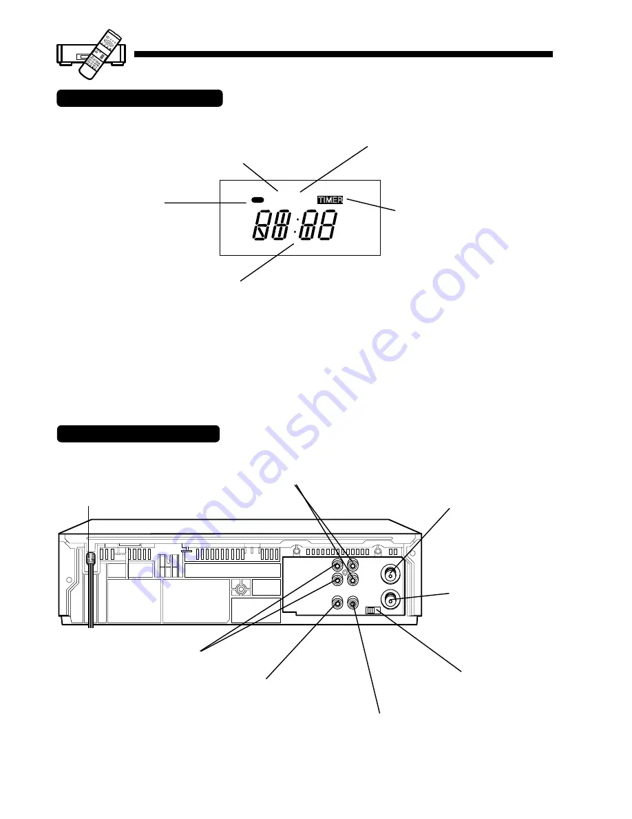
Rear View of the VCR
VCR Indicator
Appears when the VCR/TV
selector is set to VCR.
Power Indicator
This indicator lights
when power is turned on.
Video Input Connector
TIMER
VCR
Hi-Fi
A
M
Clock/Status/Channel Display
Displays the current time.
Briefly displays VCR status when function button is pressed.
Also, briefly displays the channel number selected, “L” when
channel button is pressed or select a line input.
Timer Indicator
This indicator lights when the VCR
is set for a Timer Recording, or if a
length is set for normal recording.
It flashes when a Timer Recording
has been set, but a tape has not
been inserted into the VCR.
Hi-Fi Indicator
When Hi-Fi audio is monitored or
played back, this indicator appears.
IN FROM
ANT.
VHF/UHF
OUT TO TV
VIDEO 1
AUDIO 1
3 CH. 4
L
OUT
R
IN
Audio Output Connector (L/R)
Video Output Connector
AC Power Plug
When plugged into an AC outlet,
the VCR consumes 7W of
electric power in OFF condition.
Audio Input Connector (L/R)
VHF/UHF Antenna
Input Terminal
VHF/UHF Antenna
Output Terminal
Channel 3/4 Switch
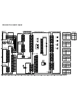
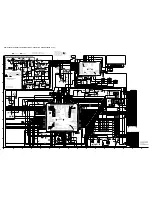
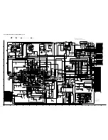
Summary of Contents for PV-4601 A
Page 14: ...Fig 2 3 14 ...
Page 27: ...Fig 11 1 1 27 ...
Page 40: ...Fig D1 40 ...
Page 42: ...Fig D2 42 ...
Page 43: ...Fig D3 43 ...
Page 44: ...Fig D4 44 ...
Page 45: ...Fig D5 45 ...
Page 46: ...Fig D7 46 ...
Page 47: ...Fig D8 47 ...
Page 51: ...Fig M2 1 Fig M2 2 51 ...
Page 53: ...Fig M4 1 53 ...
Page 77: ...Fig M19 77 ...
Page 84: ...Fig J5 84 ...
Page 85: ...Fig J6 85 ...
Page 87: ...Fig J9 87 ...
Page 88: ...Fig J10 88 ...
Page 89: ...Fig J11 89 ...
Page 90: ...Fig J12 90 ...
Page 91: ...Fig J13 91 ...
Page 92: ...Fig J15 92 ...
Page 93: ...93 ...
Page 96: ...96 ...
Page 102: ...with the holes on the Pinch Lift Cam as shown in Fig A6 102 ...
Page 103: ...103 ...
Page 105: ...Fig K1 105 ...
Page 106: ...Fig K2 106 ...
Page 107: ...Fig K3 107 ...
Page 109: ...Fig B1 109 ...
Page 114: ...Fig E1 4 3 2 HOW TO READ THE ADJUSTMENT PROCEDURES 114 ...
Page 115: ...Fig E2 115 ...
Page 134: ...R6004 ERJ6GEYJ333V MGF CHIP 1 10W 33K 134 ...
Page 136: ...R6085 ERJ6GEYJ223V MGF CHIP 1 10W 22K 136 ...
Page 140: ...C4601 ECEA1CKA100 ELECTROLYTIC 16V 10 140 ...
Page 147: ...R6065 ERJ6GEYJ223V MGF CHIP 1 10W 22K 147 ...
Page 167: ...9 11 Operation Block Diagrams 1 167 ...
Page 178: ......
Page 204: ......
Page 205: ......


