1
1
2
4
REC/TIME
3
Push SPEED to change
current recording speed.
SPEED
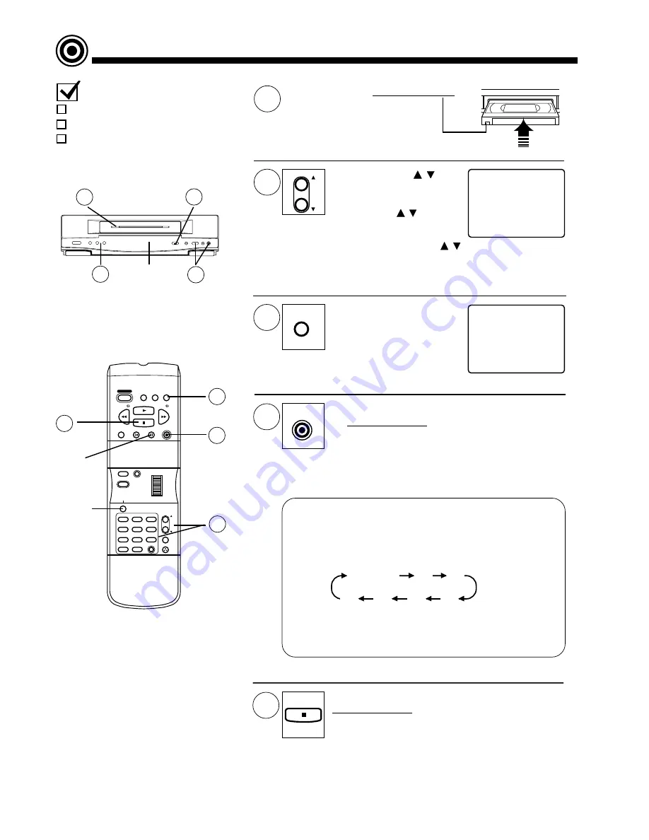
Insert a cassette with record tab.
• VCR power comes on
automatically.
STOP
CH0 2
SLP
2
5
Record On a Tape
Push VCR CH / or
NUMBERED keys to
select a channel.
• SP = Standard Play,
LP = Long Play,
SLP = Super Long Play.
VCR
CH
TRACKING
STOP
ZERO/1MIN
SLOW
PAUSE
REC/TIME
PLAY
PROG
CLEAR
MENU
DISPLAY
1
2
3
5
4
6
7
9
8
0
100
PUSH TO
SET
ROTATE TO SELECT
SPEED
VCR/TV
COUNTER
RESET
POWER
REW/
FF/
ADD/DLT
R-TUNE
SAP/Hi-Fi
VCR
CH
TRACKING
DISPLAY
5
3
4
2
4
Check list before you begin.
All connections are made.
VCR is Plugged in.
TV is turned on and set to the VCR
channel (CH3 or CH4).
• Or, push PLAY and REC/TIME on VCR.
• Push PAUSE to pause a recording in progress.
(After the VCR has been in pause mode for 5
minutes, it will stop automatically to protect the
tape and video head.)
Push REC/TIME
to start recording.
1
PAUSE
Multi
Function
Display
• Or, push CH
/
on
the VCR.
• To record from an outside
source, push VCR CH
/
to select “LINE”.
5
STOP
• Or, push STOP on the VCR.
One Touch Timer Recording (OTR)
The VCR starts recording and turns itself off at a preset time.
Continue to push REC/TIME to set the recording length.
Each Push will change the stop time as shown.
• “TIMER” lights in the Multi Function Display.
• The recording time remaining appears if the DISPLAY button
is pushed during OTR mode.
Normal Rec
0:30
1:00
1:30
2:00
3:00
4:00
Push STOP to
stop recording.
Summary of Contents for PV-4601 A
Page 14: ...Fig 2 3 14 ...
Page 27: ...Fig 11 1 1 27 ...
Page 40: ...Fig D1 40 ...
Page 42: ...Fig D2 42 ...
Page 43: ...Fig D3 43 ...
Page 44: ...Fig D4 44 ...
Page 45: ...Fig D5 45 ...
Page 46: ...Fig D7 46 ...
Page 47: ...Fig D8 47 ...
Page 51: ...Fig M2 1 Fig M2 2 51 ...
Page 53: ...Fig M4 1 53 ...
Page 77: ...Fig M19 77 ...
Page 84: ...Fig J5 84 ...
Page 85: ...Fig J6 85 ...
Page 87: ...Fig J9 87 ...
Page 88: ...Fig J10 88 ...
Page 89: ...Fig J11 89 ...
Page 90: ...Fig J12 90 ...
Page 91: ...Fig J13 91 ...
Page 92: ...Fig J15 92 ...
Page 93: ...93 ...
Page 96: ...96 ...
Page 102: ...with the holes on the Pinch Lift Cam as shown in Fig A6 102 ...
Page 103: ...103 ...
Page 105: ...Fig K1 105 ...
Page 106: ...Fig K2 106 ...
Page 107: ...Fig K3 107 ...
Page 109: ...Fig B1 109 ...
Page 114: ...Fig E1 4 3 2 HOW TO READ THE ADJUSTMENT PROCEDURES 114 ...
Page 115: ...Fig E2 115 ...
Page 134: ...R6004 ERJ6GEYJ333V MGF CHIP 1 10W 33K 134 ...
Page 136: ...R6085 ERJ6GEYJ223V MGF CHIP 1 10W 22K 136 ...
Page 140: ...C4601 ECEA1CKA100 ELECTROLYTIC 16V 10 140 ...
Page 147: ...R6065 ERJ6GEYJ223V MGF CHIP 1 10W 22K 147 ...
Page 167: ...9 11 Operation Block Diagrams 1 167 ...
Page 178: ......
Page 204: ......
Page 205: ......

