background image

Part Name

Remarks

Part No.

Ref. No.

Part Name

Remarks

Part No.

Ref. No.

7-4

Part Name

Remarks

Part No.

Ref. No.

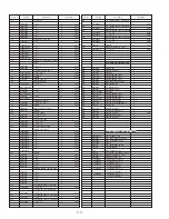
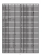
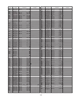
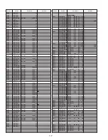
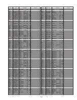
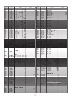
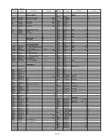
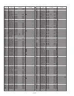
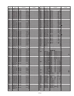
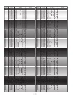
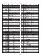
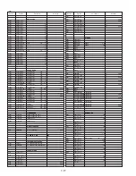
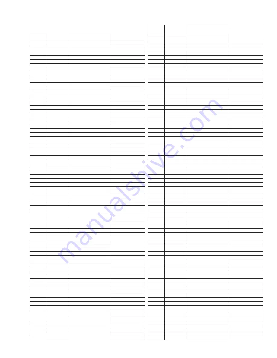
ELECTRICAL REPLACEMENT
PARTS LIST

PRINTED CIRCUIT BOARD ASSEMBLY

bN==========sbmpPMQMbN======j^fk=`K_K^K====================

=bKpKaK=oqi======^hbf

============E=^=F

bN==========sbmpPMQO_N======j^fk=`K_K^K====================

=bKpKaK=oqi======^hbf

============E=_I`=F

bN==========sbmpPMQM`N======j^fk=`K_K^K====================

=bKpKaK=oqi======^hbf

============E=aIb=F

bN==========sbmpPMQM_N======j^fk=`K_K^K====================

=bKpKaK=oqi======^hbf

============E=c=F

bN==========sbmpPMQO^N======j^fk=`K_K^K====================

=bKpKaK=oqi======^hbf

============E=dIe=F

bN==========sbmpPMQM^N======j^fk=`K_K^K====================

=bKpKaK=oqi======^hbf

============E=f=F

bO==========sbmpQMNS^N======qs=pqbobl=`K_K^K===============

=bKpKaK=oqi======^hbf

============E=f=F

bS==========sbmpRMNOwN======eb^a=^jm=`K_K^K================

========oqi======^hbf

============E=^I_I`IcIdIe=F

bS==========sbmpRMNNwN======eb^a=^jm=`K_K^K================

========oqi======^hbf

============E=aIbIf=F

bT==========sbmpM^OR^=======grk`qflk=`K_K^K================

========oqi

bNN=========sbmpQMNQ^N======pqbobl=^jm=`K_K^K==============

========oqi======^hbf

============E=f=F

bNS=========iojSNMMOuw======qs=j^fk=`K_K^K=================

========oqi======^hbf

============E=^=F

bNS=========iojSNMMOww======qs=j^fk=`K_K^K=================

========oqi======^hbf

============E=_=F

bNS=========iojSNMMOw^======qs=j^fk=`K_K^K=================

========oqi======^hbf

============E=`=F

bNS=========iojSNMMOvw======qs=j^fk=`K_K^K=================

========oqi======^hbf

============E=a=F

bNS=========iojSNMMOv^======qs=j^fk=`K_K^K=================

========oqi======^hbf

============E=b=F

bNS=========iojSNMMO_w======qs=j^fk=`K_K^K=================

========oqi======^hbf

============E=c=F

bNS=========iojSNMMO`w======qs=j^fk=`K_K^K=================

========oqi======^hbf

============E=d=F

bNS=========iojSNMMO`^======qs=j^fk=`K_K^K=================

========oqi======^hbf

============E=e=F

bNS=========iojSNMMO^w======qs=j^fk=`K_K^K=================

========oqi======^hbf

============E=f=F

bNT=========iomOPMMTvw======`oq=`K_K^K=====================

========oqi======^hbf

============E=^IaIb=F

bNT=========iomOPMMTww======`oq=`K_K^K=====================

========oqi======^hbf

============E=_I`=F

bNT=========iomOPMMT^w======`oq=`K_K^K=====================

========oqi======^hbf

============E=cIf=F

bNT=========iomOPMMT_w======`oq=`K_K^K=====================

========oqi======^hbf

============E=dIe=F

MAIN C.B.A.

( A,D,E,F,I )

INTEGRATED CIRCUITS

f`NMMN======MkPNPNJoKhq=====f`I=ifkb^o=boolo=sK=abq========

!

f`PMMN======^kPQTRc_m=======f`I=ifkb^o=sfablL^rafl=mol`bpp

f`POMN======jkPUURp=========f`I=``a=Ne=abi^v==================bKpKaK

f`PPMN======i`USQPNORVRT====f`I=U_fq=jf`olmol`bpplo===========bKpKaK==========^hbf

============================lpaL``s

f`QNRN======^kROSR==========f`I=ifkb^o=^rafl=^jm

============E=^IaIbIc=F

f`RPMN======^kRPSTc_========f`I=ifkb^o=vL`=pfdk^i=mol`bpp

f`SMMN======jkSTRMRU^RmO====f`I=U_fq=jf`olmol`bpplo===========bKpKaK

f`SMMO======`k^NUMNk========obbi=pbkplo=rkfq

f`SMMP======`k^NUMNk========obbi=pbkplo=rkfq

f`SMMQ======OQi`MN_LmpN=====f`I=Nh=bbm=olj=jbjlov=============bKpKaK

TRANSISTORS

nNMMN=======Op`QRPPimKhq===================================

!

============lo=Op`RNPMicSMU================================

!

nNMMO=======OpaNQRU

nNMMP=======OpaSPSEnIoIpF

nNMMQ=======Op_SQNEnIoIpF

(E1, E2, E6, E7, E11, E16, E17)

nNMMR=======Op_SQNEoIpF

nNMRN=======Op`PURO

nNMRO=======Op`VQR^EqmF=======================================================^hbf

nPMMN=======Op_TMVEoIpF=====`efm

nPMMO=======OpaSMNEoIpF=====`efm

nPPNM=======OpaSMNEoIpF=====`efm

nPPNN=======Op_TMVEoIpF=====`efm

nPPNQ=======fjuN============`ljmiu=`jm=pf=kmk=`efm

nPPNR=======rkONNO==========`efm

nQMMN=======Op_TMVEoIpF=====`efm

nQMMO=======OpaSMN^EoIpF====`efm

nQMMP=======OpaSMN^EoIpF====`efm

nQMMQ=======rkOONP==========`efm

============E=f=F

nQMMR=======rkOONR==========`efm

nQMMS=======rkONNR==========`efm

nQNMN=======Op`VQR^EqmF=======================================================^hbf

nQNRP=======OpaOORV

============E=^IaIbIc=F

nQNRQ=======rkOONO==========`efm

nRPMN=======OpaSMNEoIpF=====`efm

nRPMO=======OpaSMNEoIpF=====`efm

nRSMN=======OpaSMNEoIpF=====`efm

nRVMN=======OpaOORV

nRVPN=======OpaSMNEoIpF=====`efm

nRVRN=======Op_TMVEoIpF=====`efm

nRVRO=======OpaSMNEoIpF=====`efm

nRVRP=======Op_TMVEoIpF=====`efm

nSMMO=======OpaSMNEoIpF=====`efm

nSMMP=======Op_TMVEoIpF=====`efm

nSMMQ=======Op_TMVEoIpF=====`efm

nSMMR=======Op`VQR^EqmF=======================================================^hbf

nSMMS=======aq^NQPbp

nSMMT=======Op`VQR^EqmF=======================================================^hbf

nSMMU=======sbhpRROO========melql=pbkplo=rkfq

nSMMV=======sbhpRROO========melql=pbkplo=rkfq

DIODES

aNMMN=======pNt_^QM========================================

!

============lo=pNt_^SM=====================================

!

============lo=pNt_^SM_====================================

!

aNMMO=======bo^NUJMQ

aNMMP=======bo^NUJMQ

aNMMR=======bo^NUJMQ

aNMMS=======orOvuic`N

aNMMT=======bo^NUJMQ

aNMMU=======bhNP

aNMNN=======j^QMRNke========wbkbo=====================RKNs

aNMNO=======j^URU

aNMNP=======j^NSR

aNMNR=======oaNUc_==========wbkbo======================NUs=

!

aNMNS=======j^NSR

aNMRN=======j^QNMMk=========wbkbo======================NMs

aNMRO=======j^NSR

aNMRP=======j^NSR

aNMRQ=======ewPMJPqa========wbkbo======================PMs

aPPMN=======j^PTOg==========`efm==============================================^hbf

aPPMO=======j^NSR

aQMOO=======j^QMRSJj========wbkbo=====================RKSs

============E=f=F

aQNRO=======j^QNOMJj========wbkbo======================NOs

============E=^IaIbIc=F

aQNRR=======j^QMRSJj========wbkbo=====================RKSs

============E=^IaIbIc=F

aQRVN=======oaVKNbt=========wbkbo=====================VKNs

============E=f=F

aRPMQ=======j^NSR

aRRMN=======j^QMSOJi========wbkbo=====================SKOs

aRRMO=======j^NSR

aRRMP=======j^NSR

aRRMQ=======j^NSR

aRRMR=======j^NSR

aRSMN=======j^NSR

aRVRN=======j^NSR

aRVRO=======j^QMRNJj========wbkbo=====================RKNs

aRVRP=======j^NSR

aRVRQ=======j^NSR

Summary of Contents for PV-M1327

Page 1: ... lbs 11 8 kg 49 95 lbs 22 67 kg 50 12 lbs 22 75 kg 50 67 lbs 23 kg ITEM SPECIFICATION 123456 Head 2 rotary heads helical scanning system 4 rotary heads helical scanning system Input Level VIDEO IN Jack Phono type 1 0 Vp p 75Ω unbalanced Signal to Noise Ratio SP more than 43 dB LP SLP more than 41 dB Horizontal Resolution Color Monochrome more than 230 lines Head Normal Mono 1 stationary head Input...

Page 2: ...iagram 3 2 Stereo Amp Schematic Diagram 3 4 Main I Power Supply System Control Servo Operation Schematic Diagram 3 7 Main II Signal Process OSD Audio Audio Amp Schematic Diagram 3 11 Main III TV Y C Process Schematic Diagram 3 15 Main IV Power Supply Schematic Diagram 3 19 TV Stereo Schematic Diagram 3 19 TV Main Schematic Diagram 3 23 CRT Schematic Diagram 3 25 UHF VHF Tuner TV Demodulator Schema...

Page 3: ...servicing make the following leakage current checks to prevent the customer from being exposed to shock hazards LEAKAGE CURRENT COLD CHECK 1 Unplug the AC cord and connect a jumper between the two prongs on the plug 2 For physically operated power switches turn power on Otherwise skip step 2 3 Measure the resistance value with an ohmmeter between the jumpered AC plug and each exposed metallic cabi...

Page 4: ...therwise harmless motion such as the brushing together of your clothes fabric or the lifting of your foot from a carpeted floor can generate static electricity ESD sufficient to damage an ES device NOTE to CATV system installer This reminder is provided to call the CATV system installer s attention to Article 820 40 of the NEC that provides guidelines for proper grounding and in particular specifi...

Page 5: ...1 3 ...

Page 6: ...1 4 ...

Page 7: ...1 5 ...

Page 8: ...1 6 ...

Page 9: ...it Position Mechanism position EJECT REV PLAY CUE SLOW STILL FF REW BRAKE STOP STBY CASSETTE DOWN position code 1 2 3 4 5 6 7 8 9 A B C D Mode Select SW REV STOP EJECT A B C FF REW BRAKE LOAD UNLOAD CASSETTE DOWN PLAY CUE SLOW STILL 1 D 2 B 9 7 5 6 8 A C 4 3 SERVICE NOTES Simplified Fault Finding Data SimplifiedSelf DiagnosticSystemfacilitatesfindingthecause of the fault 4 digit fault code will be...

Page 10: ...Main C B A Service Position The Basic Service Position does not require the use of Exten sion Cables However for more extensive servicing Exten sion Cables should be used 1 Basic Service Position Service Position 1 1 Remove Rear Cover VCR Unit Stereo Amp C B A Model I and Top Shield Plate Ass y 2 Then place VCR Unit as shown Fig 2 1 CAUTION HOT CIRCUIT Primary circuit exists on the Main C B A and ...

Page 11: ...ect Degaussing Coil Connector CAUTION HOT CIRCUIT DO NOT touch Power curcuit during service 2 Service Position with Extension Cable Kit In Service Position with Extension Cable Kit mechanism check from the Bottom Side of Mechanism Chassis and Capstan Stator Unit Capstan Motor Drive Loading Motor Drive Circuit check with power on condition can be performed Fig 3 1 CAUTION HOT CIRCUIT Primary circui...

Page 12: ...rvice Position with Extension Cables 1 Remove Rear Cover VCR Unit Stereo Amp C B A Model I Top Shield Plate Ass y Mechanism Chassis and Cassette Up Ass y 2 Connect the Extension Cables as follows Extension Cable Kit VUZS0002 Fig 3 2 Note 3 types of Extension Cable 2 are included in this kit Since there is a difference in the number of P3501 Head Amp C B A pins between 2 Head 4 Head and Hi Fi model...

Page 13: ...pe into the cassette by rotating the Center Clutch Unit counterclockwise 5 Unhook Spring A of the Drive Rack Unit 6 Remove Screw A 7 Lift the Drive Rack Unit up so that the slot clears the guide tab WhilepullingtheDriveRackUnitoutfarenoughsothat it clears the Drive Rack Arm slide the Drive Rack Unit as indicatedbythearrowtoremovethecassettetapefromthe Cassette Up Ass y 9 Check the cause of mechani...

Page 14: ...plying 10 0VDC Power Supply again 6 After completing the removal procedure resolder Jumper J6004 Electrical Method Electrical method can only be performed when the mechanism is moved by rotating the Main Cam Gear CAUTION If loading dose not start in approx 2 seconds after DC Power Supply is applied DO NOT continue to apply DC Power Supply Instead perform Manual Method Method 1 1 Remove the solder ...

Page 15: ...ke Connector P1002 P4591 Flyback Transformer Clamper Clamper Clamper Frame Anode Cap Deflection Yoke Degaussing Coil Grounding Wire PK3 PK2 PK1 Clamper 45 Red White Speaker R TV Main C B A VCR Main C B A Deflection Yoke Connector P1002 P4592 P4605 P4602 P4301 P4604 Flyback Transformer Clamper Clamper Clamper Frame TV Stereo C B A Stereo Amp C B A Anode Cap Deflection Yoke Degaussing Coil Grounding...

Page 16: ...YSENSITIVE ES DEVICES section of this service manual ReplacementProcedureforLeadless Chip Components Thefollowingproceduresarerecommendedforthereplacement of the leadless components used in this unit 1 Preparation for replacement a Soldering Iron Use a pencil type soldering iron that uses less than 30 watts b Solder EutecticSolder Tin63 Lead37 isrecommended c Soldering time Do not apply heat for m...

Page 17: ...ng mecanism manually it can be confirmed without a cassette To release from this mode remove the jumper between TP6001 and GND Defeating the Auto Tracking To defeat the Auto Tracking Function place the instrument in the STOP mode and place a jumper between TP6003 and TP6009 on the Main C B A The tracking will be placed in the neutral position How to set Tracking to the Neutral Position Ejecting th...

Page 18: ...the schematic diagram CAUTION Once chip parts are removed they must not be reused Always use a new part when installing a chip part 1st 2nd 3rd B E C 1 CRT C B A 1 TV STEREO C B A E B C LA7837 2SD1555LBMTV 2SD2499LBMA STR30130 2SC3063 AN7420 1 2SD601 2SD601A 2SB709 TV MAIN C B A E C B E B C 2SD2375 2SC3852 2SC4533LP KT 2SC5130LF608 1 2 4 3 E C B AN5265 AN3809K 1 ON3131 R KT 2SC945A 2SA733 2SC1473 ...

Page 19: ...embly Flowchart Perform all disassembly procedures in the order described in the DisassemblyFlowchart shownbelow Whenreassembling use the reverse procedure CAUTION Disconnect AC plug before disassembly Fig D1 Swivel Unit Model A D E Disassembly Procedure 1 While pushing one of the Locking Tabs A outward pull that portion of the Swivel Unit free from the unit 2 Repeat step 1 for other Locking Tabs ...

Page 20: ...G H Disconnect the Connector P4591 on the Main C B A and remove the leads from the clampers Model I Disconnect 2 Connectors P4604 and P4605 on the Stereo Amp C B A and remove the leads from the clampers Fig D4 1 6 Model A B C D E Slightly lift up the rear side of the VCR Unit to release Tabs B Model F G H I Slightly lift up the rear side of the VCR Unit to release Tabs B and C 7 Slide the VCR Unit...

Page 21: ...ectors P4592 on the Main C B A and P4301 on the TV Stereo C B A 2 Release 3 Clampers A on the TV Stereo C B A Then remove the Stereo Amp C B A Fig D6 VCR Unit VCR Unit Holes A Guide Tabs A Bottom view of VCR Unit Tabs B Tabs C Fig D4 2 Reassembly Notes 1 Installation of VCR Unit 1 WheninstallingtheVCRUnit swingtheCassetteDoor Lid all the way open until the Cassette Door tab clears the Opener Lever...

Page 22: ...LockingTabs B and A C Cord from the frame Fig D8 Clampers B Cassette Up Ass y Screws B Clampers B Clamper Clamper 6 Top Shield Plate Ass y Top Shield Plate Ass y Disassembly Procedure 1 Release the 2 Clampers B on the Top Shield Plate Ass y and remove the leads from the clampers 2 Remove 3 Screws B Then remove the Top Shield Plate Ass y Fig D7 1 Reassembly Notes 1 When installing the Top Shield Pl...

Page 23: ...osition Fig D10 2 2 Be sure to install the Mechanism Chassis Unit straight onto the Main C B A so that the Sensor LED clears the hole in the Mechanism Chassis Unit 3 Be sure that 4 Connectors P2531 P2552 P3501 and P4001 are aligned and seated securely Frame Screw D A 8 VCR Chassis Unit Locking Tab C Screw D Model A B C D E Screws C Screw with Washer B Screw with Washer B Screw E Screw D Holder Uni...

Page 24: ...crew G 3 Unhook Spring A 4 Slide the Cassette Up Ass y towards the front to release Tab C Then lift it up and remove Fig D11 Reassembly Notes 1 Installation of Cassette Up Ass y 1 Confirm that the 3 pins and Tab C under the Cassette Up Ass y are in each of the 4 Guide Holes on the Mechanism Chassis when installing the Cassette Up Ass y Then slide the Cassette Up Ass y towards the back 2 Tighten 2 ...

Page 25: ...r A Step Loc No Order of steps in procedure Part Part to be removed or installed Prior Step s Steps to be completed prior to the current step Disassembly Method This chart indicates Step Location No of Parts to be serviced and prior steps to gain access items to be serviced when disassembling When reassembling perform the step s in the reverse order Cylinder Unit 3 5 3 4 5 3 4 5 7 9 Upper Cylinder...

Page 26: ...ion of Cylinder Unit 1 Install the Cylinder Unit so that the 2 holes on the lower surface of the Cylinder Unit fit over the 2 Guide Pins on the Cylinder Base and loosely secure it with 3 Screws A 2 Install the Head Amp C B A so that the hole on the Head Amp C B A lines up with the hole on the chassis and secure it with 2 Screws with Washers A 3 Position the Cylinder Unit so that foil patterns of c...

Page 27: ...Cylinder 2 After installing perform the Tape Interchangeability Adjustment Confirmation Procedures Opener Piece Pinch Arm Unit Motor Block Ass y and Audio Control Head Unit Disassembly Procedure 1 Remove the Opener Piece by pulling it upward while releasing 2 Locking Tabs A 2 Pull up on the Pinch Arm Unit 3 Release 3 Locking Tabs B and remove Screw with Washer C Then remove the Motor Block Ass y a...

Page 28: ...le on chassis as shown Through hole B E indicates the EJECT position Fig J5 3 2 Installation of Main Cam Gear and Main Cam Push Nut 1 Position the chassis upside down placing a Support under the Main Cam Gear Install the Main Cam Push Nut with Needlenose Pliers etc so that it is flush with the chassis There may be some slight scratches on the Shaft of Main Cam Gear when removing the Main Cam Gear ...

Page 29: ...P5 Arm Unit 2 Turn the Main Lever Drive Arm fully counterclockwise as shown 3 Pull up on the Main Lever Drive Arm Fig J7 1 Reassembly Notes 1 Alignment of Main Lever Drive Arm 1 Install the Main Lever Drive Arm so that the hole C is alignedwiththeholeontheChassisasshown Through hole C Fig J7 2 11 Main Lever Drive Arm 10 P5 Arm Unit turn Main Lever Drive Arm Chassis Through Hole C Loading Rack Shaf...

Page 30: ...ging Lever A and T Reel Table Disassembly Procedure 1 Remove the T Brake Unit while releasing Locking Tab E located under the chassis 2 Remove Cut Washer A Then pull up on the Changing Lever A and remove 3 Pull up on the T Reel Table Fig J8 1 Reassembly Notes 1 How to distinguish between S Reel Table and T Reel Table Fig J8 2 2 Adjustment of T Reel Table 1 After installing perform the Reel Table H...

Page 31: ...e SS Brake Arm Unit Fig J11 1 Reassembly Notes 1 Installation of Capstan Rotor Unit 1 Insert the Capstan Rotor Unit Shaft to the hole of the Capstan Holder Unit 2 Place a support under the Capstan Rotor Unit shaft Install the Stopper Be careful not to scratch the shaft or Capstan Holder Unit 3 Remove the support Press the top end of the shaft down so that the Stopper is properly positioned You sho...

Page 32: ...y as a replacement part Capstan Rotor Unit Capstan Holder Unit and Stopper are not reusable Install all new parts BecauseeveninvisiblescratchesontheCapstanRotor Unit shaft and the Capstan Holder Unit made when cutting the Stopper could cause tape path instability 3 Adjustment of FG Head 1 After installing perform the FG Head gap Adjustment procedures 29 PCB Holder 27 Capstan Stator Unit IC2501 CAU...

Page 33: ... Unit Changing Gear Locking Tab J 30 T Loading Arm Unit 31 S Loading Arm Unit Loading Rack Through Hole Loading Rack Triangle Indent T Loading Arm Unit S Loading Arm Unit Arrow Through Hole T Loading Arm Unit and S Loading Arm Unit Disassembly Procedure 1 Remove the T Loading Arm Unit by pulling it up while releasing Locking Tab J 2 Pull up on the S Loading Arm Unit Fig J13 1 Reassembly Notes 1 Al...

Page 34: ...UP ASS Y Top Plate Wiper Arm Unit and Holder Unit Disassembly Procedure 1 Remove Top Plate by releasing 2 Locking Tabs A on the left side and 2 Locking Tabs B on the right side of the Top Plate 2 Remove Wiper Arm Unit by releasing 2 Locking Tabs C Then remove the Holder Unit Fig K1 1 Loading Rack Unit Disassembly Procedure 1 Slide the Loading Rack Unit as indicated by the arrow Then pull up on the...

Page 35: ...Wiper Arm Unit so that the hole on the Wiper Arm Unit is aligned with the hole on the Drive Rack Unit Fig K1 2 2 Installation of Holder Unit 1 Turn the Wiper Arm Unit so that the grooves on each end are aligned with the grooves on Side Plate L and R 2 Insert Holder Unit boss A and B into the grooves 3 Finally in the EJECT Position confirm that the protrudence on the Wiper Arm Unit is aligned with ...

Page 36: ...ent Driver VFK1301 Silicon Grease VUZS0002 TSM10032 2 Model F G H I Extension Cable Kit VFK27 Head Cleaning Stick VFK0330 H Position Adjustment Driver VFKS0081 Grease Video Audio Color Bar Monoscope 6kHz MONO Extension Cable 2 VUVS0005 for 2 Head Model Mode Select SW Ass y VUVS0001 Extension Cable 2 VUVS0004 for 4 Head Model Extension Cable 2 VUVS0003 for Hi Fi Model Extension Cable 1 VUVS0002 8 p...

Page 37: ...tween the left edge of the P1 Post and the right edge of the Tension Post Make sure that the center of the Hex Wrench hole is within Area A 5 After adjustment remove the Hex Wrench 6 Press the STOP EJECT button to place the unit in the EJECT Mode 7 Release the unit from the Service Mode Refer to Service Mode in the Service Notes section of this manual Fig M2 MECHANICAL ADJUSTMENT CLEANING PROCEDUR...

Page 38: ...erintotapepathandmeasuretheback tension 3 If the reading is out of specification make sure that there is no dust or foreign material between the Tension Band of Tension Arm Unit and the Reel Table If cleaning does not correct the tension measurement replace the Tension Spring and the Tension Arm Unit Fig M3 1 Note 1 Be sure that the three probes of the meter are all in solid contact with the tape ...

Page 39: ...G Signal Symptom of Misadjustment If the FG Signal is not properly picked up Servo Operation cannot be achieved Equipment Required Oscilloscope Specification 0 13 0 02mm 1 Remove the VCR Chassis Unit and then place it upside down 2 Remove the Main C B A 3 Slightly loosen Black Screw A Then set the Screwdriver 1 or 2 Phillips Driver into the Hole A Turn the screwdriver counterclockwise until the FG...

Page 40: ...tion the Post Adjustment Plate over the reels 3 Place the fixture on the Post Adjustment Plate and zero the fixture DO NOT use the cut out portion of the post adjustment plate Fig M6 1 4 Lower each post below the top edge of the Post Adjustment Plate Then raise each post until it contacts the foot of the Reel Table Height Fixture For proper adjustment the foot of that should be positioned as shown...

Page 41: ...ystem Control Section of the Main C B A to defeat Auto Tracking 3 Eject the tape and insert it again to access the Neutral Tracking position 4 Play back the alignment tape 5 With Post Adjust Driver adjust P2 and P3 post height so that the envelope waveform V1 V max is 0 7 or more becomes as flat as possible No envelope drop If the envelope drop appears on the left half of the waveform adjust P2 po...

Page 42: ...peration cannot be achieved A Blue screen will be seen in Playback This confirmation is required when the A C Head is replaced 1 Play back a T120 cassette tape and check that the lower edge of the tape runs approximately 0 25 mm above the lower edge of the A C Head 2 If necessary adjust Black Screws A and B clockwise to lower the tape or counterclockwise to raise 4 A C HEAD AZIMUTH ADJUSTMENT Purp...

Page 43: ...e either clockwise or counterclockwise so that the envelope is at maximum 4 Before finding the center of the maximum period of the envelope rotatethefixturebackandforthslightlytoconfirm the limits on either side of the maximum period 5 Push the Tracking Control Up Button on the Remote Control several times count the number of times pushed until the maximum envelope is reduced to 1 2 6 Reset the tr...

Page 44: ...nge 0 01 to 50V 4 Plastic Tip Driver and Non Metal Driver 5 Isolation Transformer Variable 6 VHS Alignment Tape VFMS0003H6 7 Degaussing Coil 8 White Pattern Generator 9 White Balance Meter HOW TO READ THE ADJUSTMENT PROCEDURES Fig E1 EVR Electronic Variable Register Adjustment with the remote control This unit has electronic technology using I2 C Bus concept The following control functions are adj...

Page 45: ...from channel 2 2 Playback the VHS alignment tape and adjust the R6201 PG SHIFTER so that the leading edge of the head switching pulse is placed 6H 1H 0 38 0 06msec before the start of the vertical sync pulse Fig E3 3 Press CH UP DOWN key on the remote control to adjust the value of the selected control Fig E2 4 Note You can select a desired channel by using the numbered keys on the remote control ...

Page 46: ...isplay the MAIN menu 2 Select TV and then press the MENU key to display the SET UP TV menu 3 Press the CH UP DOWN key to select the VIDEO ADJUST Then press the VOL UP key to display the VIDEO ADJUST mode 4 Press the CH UP DOWN key to select NORMAL Then press the VOL UP key to return the levels to the factory settings 2 Supply a Crosshatch Pattern Signal to the Video Input Jack 3 Connect the Oscill...

Page 47: ...B TINT EVR Specification A 1 6 0 15Vp p Input Video Input Jack Rainbow Color Bar Mode STOP Equipment Oscilloscope 1 Reset the control levels to the factory set levels using the remote control Refer to Step 1 in the SUB CONTRAST ADJUSTMENT 2 Supply the Rainbow Color Bar signal to Video Input Jack 3 Select SUB BRIGHT in EVR adjustment mode Then after making a note of the original value adjust to the...

Page 48: ...de the Deflection Yoke back slightly without rotating it until the distorted color areas disappear from the screen 9 Supply a Crosshatch Pattern Signal to Video Input Jack again Confirm that the Center Bar is at the horizontal center line of the CRT and the V Center Bar is at the verticalcenterlineoftheCRT Then tightentheExpansion Screw 10 Press DISPLAY key Service Switch on the remote control for...

Page 49: ...ment Oscilloscope 1 Supply a Crosshatch Pattern Signal to the Video Input Jack 2 Hold the Deflection Yoke and wiggle it up and down to produce the correct Crosshatch Pattern position Fig E9 1 3 Hold Deflection Yoke and wiggle it horizontally right to left to produce the correct Crosshatch Pattern position Fig E9 2 4 Insert three wedges to maintain the correct Crosshatch Pattern Position Fig E9 3 C...

Page 50: ...he top 3rd line is just in view 3 Confirm that the 10th dotted line is in view and that the 11th line is out of view If the lines are not positioned correctly readjust V SIZE so that the top 3rd line is within 2mm from the top edge of the screen Confirm that the 10th dotted line is in view and that the 11th line is out of view 4 Select H CENTER in EVR adjustment mode and adjust so that A is approx...

Page 51: ...DRIVE EVR B DRIVE EVR R CUT OFF EVR G CUT OFF EVR B CUT OFF EVR Specification Refer to descriptions below Input Video Input Jack White Pattern Signal Mode STOP Equipment Oscilloscope White Balance Meter Method 1 1 Supply a White Pattern Signal to the Video Input Jack 2 Press DISPLAY key Service Switch on the remote control for collapse scan 3 Turn the SCREEN CONTROL on Flyback Transformer fully co...

Page 52: ...est Points on Main C B A TP3002 TP4002 TP6001 TP6003 TP6009 TP6205 Video signal REC PB video envelope signal Normal Audio signal Service Test Point inhibit sensors defeat auto tracking function connect to 5V TP6009 5V Head SW Test Point Information Test Point with a Test Pin Test Point with a jumper wire across a hole in the P C B Test Point with no Test Pin CRT C B A TV Stereo C B A Model I TP50 ...

Page 53: ...CESS SECTION Main C B A Model F G H I VOLUME UP PLAY REW REVIEW GAME REC TIME FF CUE VOLUME DOWN CH DOWN CH UP FM TV Model F I PG SHIFTER R6201 STOP EJECT Component Side J6004 TP6205 TP6003 TP6001 TP6009 TP3002 TP3001 UNLOADING J6005 TP4002 TV Main C B A Component Side 1 5 PK5 5Pin PK2 ...

Page 54: ......

Page 55: ......

Page 56: ......

Page 57: ......

Page 58: ......

Page 59: ......

Page 60: ......

Page 61: ......

Page 62: ......

Page 63: ......

Page 64: ......

Page 65: ......

Page 66: ......

Page 67: ......

Page 68: ......

Page 69: ......

Page 70: ......

Page 71: ......

Page 72: ......

Page 73: ......

Page 74: ......

Page 75: ......

Page 76: ......

Page 77: ......

Page 78: ......

Page 79: ......

Page 80: ......

Page 81: ......

Page 82: ......

Page 83: ......

Page 84: ......

Page 85: ......

Page 86: ......

Page 87: ......

Page 88: ......

Page 89: ......

Page 90: ......

Page 91: ......

Page 92: ......

Page 93: ......

Page 94: ......

Page 95: ......

Page 96: ......

Page 97: ......

Page 98: ......

Page 99: ......

Page 100: ......

Page 101: ......

Page 102: ......

Page 103: ......

Page 104: ......

Page 105: ......

Page 106: ......

Page 107: ......

Page 108: ......

Page 109: ......

Page 110: ......

Page 111: ......

Page 112: ......

Page 113: ......

Page 114: ......

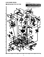
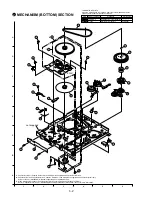
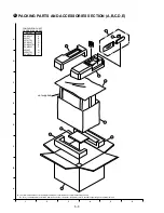
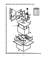
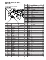
Page 115: ...ome Ref No will be skipped Be sure to make your orders of replacement parts according to the parts list Mark Kind of Lubricant Availability Part Number Silicon Grease Available from Factory VFK1301 Spindle Oil Purchase from Local Supplier Grease Available from Factory VFKS0081 401 414 24 23 12 22 20 19 21 18 5 415 10 415 9 3 27 28 E6 424 11 13 429 16 17 1 26 4 25 MECHANISM TOP SECTION 417 not supp...

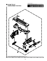
Page 116: ...or Unit Capstan Holder Unit and Stopper are supplied as a Capstan Rotor Kit only 2 Capstan Stator Unit Capstan Rotor Unit Capstan Holder Unit and Stopper are supplied as a Capstan Stator Kit only However IC2501 AN3845SC is available separately as a replacement part 3 When installing the IC2501 or Capstan Stator Unit be sure to apply Silicon Grease VFK1301 Refer to Capstan Stator Unit of Disassembl...

Page 117: ...Procedure of Mechanical Section for more information 62 64 67 70 61 68 66 65 63 4 LUBRICATION POINTS When the marked parts are replaced apply the recommended lubricants or adhesive for better maintenance of the unit Mark Kind of Lubricant Availability Part Number Silicon Grease Available from Factory VFK1301 Spindle Oil Purchase from Local Supplier Grease Available from Factory VFKS0081 ...

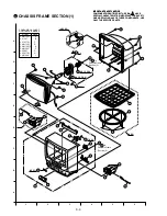
Page 118: ...COMPONENTS USE ONLY THE SPECIFIED PARTS IMPORTANT SAFETY NOTICE COMPONENTS IDENTIFIED BY THE SIGN HAVE SPECIAL CHARACTERISTICS IMPORTANT FOR SAFETY WHEN REPLACING ANY OF THESE COMPONENTS USE ONLY THE SPECIFIED PARTS To A in Chassis Frame Section 2 A To B in Chassis Frame Section 2 B 73 74 77 78 35 95 94 94 90 446 119 445 445 443 445 445 169 119 443 446 446 446 92 48 93 71 83 92 93 84 82 81 72 38 I...

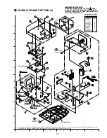
Page 119: ...FETY NOTICE COMPONENTS IDENTIFIED BY THE SIGN HAVE SPECIAL CHARACTERISTICS IMPORTANT FOR SAFETY WHEN REPLACING ANY OF THESE COMPONENTS USE ONLY THE SPECIFIED PARTS To A in Chassis Frame Section 1 A COMPARISON CHART OF MODELS MARKS MODEL MARK PV M1327 VV1307 VV1317W PV M1347 PV M1357W PV M2037 VV2007 VV2017W PV M2047 A B C D E F G H I 96 91 97 98 E2 420 404 460 402 449 449 449 460 404 432 402 153 1...

Page 120: ...a complete assembly unit only Do not try to disassemble the Infrared Remote Control Unit However the battery cover is available separately as a replacement part not supplied COMPARISON CHART OF MODELS MARKS MODEL MARK PV M1327 VV1307 VV1317W PV M1347 PV M1357W PV M2037 VV2007 VV2017W PV M2047 A B C D E F G H I 123 100 126 125 56 118 132 131 121 6 122 ...

Page 121: ...s available as a complete assembly unit only Do not try to disassemble the Infrared Remote Control Unit However the battery cover is available separately as a replacement part not supplied COMPARISON CHART OF MODELS MARKS MODEL MARK PV M1327 VV1307 VV1317W PV M1347 PV M1357W PV M2037 VV2007 VV2017W PV M2047 A B C D E F G H I 123 100 127 128 130 129 56 6 ...

Page 122: ...UNIT The UHF VHF TUNER TV DEMODULATOR UNIT replacement part is available as a complete assembly unit only 5 The Infrared Remote Control Unit Ref No 123 replace ment part is available as a complete assembly unit only Do not try to disassemble the Infrared Remote Control Unit However the battery cover is available separately as a replacement part 6 Cut Washers Ref No 416 and 417 are not reusable If ...

Page 123: ...bi ihdSMNMM E IaIb F Q hbf UN mltbo _rqqlk i_uSNMOP E Ia F Q hbf i_uSNMMV E _ F Q hbf i_uSNMOT E F Q hbf i_uSNMPN E b F Q hbf i_uSNMMN E cIf F Q hbf i_uSNMMR E d F Q hbf i_uSNMNT E e F Q hbf UO e sli _rqqlk i_uSNMOR E Ia F Q hbf i_uSNMNM E _ F Q hbf i_uSNMOU E F Q hbf i_uSNMPP E b F Q hbf i_uSNMMP E cIf F Q hbf i_uSNMMS E d F Q hbf i_uSNMNU E e F Q hbf The complete Exploded Views are shown in this...

Page 124: ...eflk ofdeqIpqvolcl j imgSNMMR E I_I IaIb F S hbf NOS qlm rpeflk ibcqIpqvolcl j imgSNMMS E I_I IaIb F S hbf NOT qlm rpeflk colkqJiIpqvolcl j imgSNMMN E cIdIeIf F S hbf NOU qlm rpeflk colkqJoIpqvolcl j imgSNMMO E cIdIeIf F S hbf NOV qlm rpeflk ob oJiIpqvolcl j imgSNMMP E cIdIeIf F S hbf NPM qlm rpeflk ob oJoIpqvolcl j imgSNMMQ E cIdIeIf F S hbf NPN _lqqlj rpeflk colkqIpqvolcl j imgSOMMR E I_I IaIb F...

Page 125: ... RPMN kRPSTc_ f I ifkb o vL pfdk i mol bpp f SMMN jkSTRMRU RmO f I U_fq jf olmol bpplo bKpKaK f SMMO k NUMNk obbi pbkplo rkfq f SMMP k NUMNk obbi pbkplo rkfq f SMMQ OQi MN_LmpN f I Nh bbm olj jbjlov bKpKaK TRANSISTORS nNMMN Op QRPPimKhq lo Op RNPMicSMU nNMMO OpaNQRU nNMMP OpaSPSEnIoIpF nNMMQ Op_SQNEnIoIpF E1 E2 E6 E7 E11 E16 E17 nNMMR Op_SQNEoIpF nNMRN Op PURO nNMRO Op VQR EqmF hbf nPMMN Op_TMVEoI...

Page 126: ...UQ bogSdbvgOOOs jdc efm NLNMt OKOh oPMUR bogSdbvgNUNs jdc efm NLNMt NUM oPMVN bogSdbvgTRMs jdc efm NLNMt TR oPPMN bogSdbvMoMMs jdc efm NLNMt M oPPMO bogSdbvMoMMs jdc efm NLNMt M oPPMP bogSdbvMoMMs jdc efm NLNMt M oPPMQ bogSdbvgOOOs jdc efm NLNMt OKOh oPPMR bogSdbvgOOOs jdc efm NLNMt OKOh oPPMS bogSdbvMoMMs jdc efm NLNMt M oPPMT bogSdbvgQTNs jdc efm NLNMt QTM oPPMU bogSdbvgNMOs jdc efm NLNMt Nh E f...

Page 127: ...LNMt RKSh oRSMQ bogSdbvgNROs jdc efm NLNMt NKRh oRSNM bogSdbvgNMOs jdc efm NLNMt Nh oRSNN bogSdbvgUOOs jdc efm NLNMt UKOh oRSNO bogSdbvgUOOs jdc efm NLNMt UKOh oRSNP bogSdbvgQTOs jdc efm NLNMt QKTh oRVMN bonNO gOTMm crpb NLOt OT oRVMO bogSdbvgNMOs jdc efm NLNMt Nh oRVPN bogSdbvgQTOs jdc efm NLNMt QKTh oRVPO bogSdbvgNMNs jdc efm NLNMt NMM oRVPP bogSdbvgNMNs jdc efm NLNMt NMM oRVRN bogSdbvgQTPs jdc ...

Page 128: ...KMN lo s hpbjaNMPmw bo jf HUMBJOMB NORs MKMN lo s hpbsaNMPmw bo jf HUMBJOMB NORs MKMN hbf lo s hpdhaNMPnw bo jf HUMBJOMB NORs MKMN lo s hpdjaNMPnw bo jf HUMBJOMB NORs MKMN lo s hpqhdNMPwv bo jf HUMBJOMB NORs MKMN lo s hpqjdNMPwv bo jf HUMBJOMB NORs MKMN lo s hprhaNMPjv bo jf HJOMB NORs MKMN lo s hprjaNMPjv bo jf HJOMB NORs MKMN NMMO b haopPPOjba bo jf HJOMB NORs PPMMm lo b hjopPPOjbv bo jf HJOMB N...

Page 129: ...Ps QT QMMV b b N h NMM bib qolivqf NSs NM QMNM b rsNbPPPh_k efm ORs MKMPP QMNO b b Neh MNM bib qolivqf RMs N QMNP b b Mgh QTM bib qolivqf SKPs QT QMNQ b b NehpMNM bib qolivqf RMs N QMNR b rsNbNMQwck efm HUMBJOMB ORs MKN QMNU b rsNeNMPh_k efm RMs MKMN E IaIbIc F QMOO b b N h NMN bib qolivqf NSs NMM E f F QMPM b rsNbPPPh_k efm ORs MKMPP QMPO b rsNeNMPh_k efm RMs MKMN QMPP b b NehpMNM bib qolivqf RMs...

Page 130: ...iPMMN sinpeMOoSUMh SU E Ic F iPMMO bibpkNMNh NMM iPMMQ sinpeMOoOOMh OO E Ic F iPMMR sinpeMOoPVMh PV iPMNM bibpkQTMh QT iPOPN bibpkOONh OOM iPPMN sinpeMOoRoSg HJRB RKS hbf iPPMO bibpkNMNh NMM iQMMO sinpeMOoNMNh NMM iQMMQ sinpeMOoOOMh OO E IaIb F sinpeMOoNMMh NM E cIf F iQMMR sinprMSoNRPh NRj iQNMN bibpkQTNh QTM iRVMN bibpkNMNh NMM CRYSTAL OSCILLATOR uPPMN spupMOMT hbf uRRMN p_RMPcPU uRSMN spupMOMUJ...

Page 131: ...F efm nRVRO OpaSMNEoIpF efm nRVRP Op_TMVEoIpF efm nSMMO OpaSMNEoIpF efm nSMMP Op_TMVEoIpF efm nSMMQ Op_TMVEoIpF efm nSMMR Op VQR EqmF hbf nSMMS aq NQPbp nSMMT Op VQR EqmF hbf nSMMU sbhpRROO melql pbkplo rkfq nSMMV sbhpRROO melql pbkplo rkfq DIODES aNMMN pNt_ QM lo pNt_ SM lo pNt_ SM_ aNMMO bo NUJMQ aNMMP bo NUJMQ aNMMR bo NUJMQ aNMMS orOvuic N aNMMT bo NUJMQ aNMMU bhNP aNMNN j QMRNke wbkbo RKNs aN...

Page 132: ...SdbvgNUOs jdc efm NLNMt NKUh oPPUN bogSdbvgNMPs jdc efm NLNMt NMh oPPVM bogSdbvgOOOs jdc efm NLNMt OKOh oQMMN bogSdbvgNMPs jdc efm NLNMt NMh oQMMO bogSdbvgPPQs jdc efm NLNMt PPMh oQMMP bogSdbvgOONs jdc efm NLNMt OOM oQMMQ bogSdbvgPPPs jdc efm NLNMt PPh oQMMR bogSdbvgOORs jdc efm NLNMt OKOj oQMMS bogSdbvgSUNs jdc efm NLNMt SUM oQMMT boapOqgOOO OKOh oQMMU bogSdbvdOTPs jdc efm HJOB NLNMt OTh oQMMV bo...

Page 133: ...NMh oSNNP bogSdbvgQTOs jdc efm NLNMt QKTh oSNNS boapOqgRSN RSM oSNNU bogSdbvgRSPs jdc efm NLNMt RSh oSNOM boapOqgOON OOM oSNON boapOqgOON OOM oSOMN bsk v MP_NR s of _ib NMMh oSOMO bogSdbvgNMQs jdc efm NLNMt NMMh oSOMP bogSdbvgPPPs jdc efm NLNMt PPh oSOMQ bogSdbvgNMOs jdc efm NLNMt Nh oSOMR bogSdbvgOQPs jdc efm NLNMt OQh oSOMS bogSdbvgPPPs jdc efm NLNMt PPh oSOMT bogSdbvgOOPs jdc efm NLNMt OOh oSOM...

Page 134: ...MQwck efm HUMBJOMB ORs MKN POPT b rsNeNMPwck efm HUMBJOMB RMs MKMN PPMN b rsNePPMg k efm HJRB RMs PPm PPMO b rsNePPMg k efm HJRB RMs PPm PPMP b rsNbNMQwck efm HUMBJOMB ORs MKN PPMQ b b MghpQTM bib qolivqf SKPs QT PPMR b rsNeNMPwck efm HUMBJOMB RMs MKMN PPMS b rsNeOTMg k efm HJRB RMs OTm PPMT b rsNeNMM k efm HJMKORm RMs NMm PPMU b rsNeNMPwck efm HUMBJOMB RMs MKMN PPMV b b NehpMNM bib qolivqf RMs N ...

Page 135: ... jf HJOMB NSs MKN SOPN b b N h NMM bib qolivqf NSs NM FILTERS ciQMMN sicpMMNQ COILS iNMMN bicNRkMMR efde m pp cfiqbo MKR NUj lo bicNUaOVM efde m pp cfiqbo MKR NUj lo iikOPMNO efde m pp cfiqbo MKR NUj lo sinpMNRT efde m pp cfiqbo MKR NUj lo sinpMNSS efde m pp cfiqbo MKR NUj lo sinpMNST efde m pp cfiqbo MKR NUj lo sinpMNSU efde m pp cfiqbo MKR NUj iNMMO sinptMTaOOMj HJOMB OO iNMMP sinptMTaVoMj HJOMB...

Page 136: ...OON OOM oVPNM boapOqgOON OOM oVPNN bogSdbvgQTPs jdc efm NLNMt QTh oVPNO bogSdbvgQTPs jdc efm NLNMt QTh oVPNP bogSdbvgQTPs jdc efm NLNMt QTh oVPNQ bogSdbvgQTPs jdc efm NLNMt QTh oVPNS bogSdbvgQTPs jdc efm NLNMt QTh oVPNT bogSdbvgQTPs jdc efm NLNMt QTh oVPNU bogSdbvgPVPs jdc efm NLNMt PVh oVPNV bogSdbvgNMPs jdc efm NLNMt NMh oVPOM bogSdbvgNMPs jdc efm NLNMt NMh oVPOQ bogSdbvgPPPs jdc efm NLNMt PPh o...

Page 137: ...dc efm NLNMt QTh oPRMO bogSdbvgRSMs jdc efm NLNMt RS oPRMP bogSdbvgRSMs jdc efm NLNMt RS oPRMQ bogSdbvgRSMs jdc efm NLNMt RS oPRMR bogSdbvgRSMs jdc efm NLNMt RS oPRMS bogSdbvgRSNs jdc efm NLNMt RSM oPRMT bogSdbvgRSNs jdc efm NLNMt RSM CAPACITORS OSMQ b rsNbNMQh_k efm ORs MKN OSMR b rsNbNMQh_k efm ORs MKN OSMS b rsNbNMQh_k efm ORs MKN OSMT b rsNbNMQh_k efm ORs MKN OSMU b rsNbNMQwck efm HUMBJOMB ORs...

Page 138: ...RPR mQSMN lkkb qlo ppDv mQSMO sbhpRRPS mQSMO lkkb qlo ppDv mQSMQ sgmpMOSU lkkb qlo Om mQSMR sgmpMOSU lkkb qlo Om MISCELLANEOUS bQM sjupMUTS mK K_K pm bo hbf TV MAIN C B A INTEGRATED CIRCUITS f QRN i TUPT f I ifkb o sboqf i lrq f UMN pqoPMNPM f I ifkb o HNPMs obdri qlo TRANSISTORS nQPN Op TPPEqnF hbf nRMN Op NQTPJnk E I_I IaIb F Op OSRPeJ i E cIdIeIf F nRMR Op TPPEqnF hbf nRMS Op TPPEqnF hbf nRMT O...

Page 139: ...cIdIeIf F oRRU bodO kgQTNe jbq i lufab Ot QTM E I_I IaIb F bodO kgRSNe jbq i lufab Ot RSM E cIdIeIf F oRRV boapOqgNOP NOh E cIdIeIf F oRSN bonN gmNoMp crpb Nt N E I_I IaIb F bonO gmNoMp crpb Ot NKM E cIf F bonO gmOoOp crpb Ot OKO E dIe F oRTN boapOqgNMN NMM oRTO boapOqgOOO OKOh oRTP boapOqgNMM NM oRTQ boapOqgOTO OKTh oRTR boapOqgPPN PPM oRUM bodOpgQTNe jbq i lufab Ot QTM E I_I IaIb F bodOpgPPNe jb...

Page 140: ...MMs QTMMm lo b htOeQTOmrT bo jf HNMMBJMB RMMs QTMMm UMQ b hjOeQTOmbT bo jf HNMMBJMB RMMs QTMMm lo b hjOeQTOmrT bo jf HNMMBJMB RMMs QTMMm lo b htOeQTOmrT bo jf HNMMBJMB RMMs QTMMm UMR b bpOarOONbd bib qolivqf OMMs OOM lo b bqOaoOONpt bib qolivqf OMMs OOM E I_I IaIb F b bpOmrQTNed bib qolivqf NUMs QTM lo b bqOmoQTNpt bib qolivqf NUMs QTM lo b MpOmmQTN__ bib qolivqf NUMs QTM E cIdIeIf F UMS b b ObrNM...

Page 141: ... nPRP Op NQTPJnk E I_I IaIb F Op PMSPJoi E cIdIeIf F RESISTORS oPRN bodN kgmNRPs jbq i lufab Nt NRh E I_I IaIb F bodO kgNRPe jbq i lufab Ot NRh E cIdIeIf F oPRO bodN kgmNRPs jbq i lufab Nt NRh E I_I IaIb F bodO kgNRPe jbq i lufab Ot NRh E cIdIeIf F oPRP bodN kgmNRPs jbq i lufab Nt NRh E I_I IaIb F bodO kgNRPe jbq i lufab Ot NRh E cIdIeIf F oPRQ boaORqgOTO OKTh oPRR boaORqgOTO OKTh E cIf F oPRS boa...

Page 142: ...k K_K K bNT iomOPMMTvw oq K_K K bNT iomOPMMTww oq K_K K bNT iomOPMMT w oq K_K K bNT iomOPMMT_w oq K_K K bON sbnpMRVS qrkboIrecLsec ko bON sbnpMRVU qrkboIrecLsec ko bOO qpuTNRNJk loa tLmirdINOMs bOO qpuTNROJk loa tLmirdINOMs bOP sgppPPOR crpb eliabo bOQ ijeSVMMO iba eliabo bOQ ijeSVMMP iba eliabo bOR ijeOVMMN iba eliabo bOR ijeOVMMO iba eliabo bOT dmNrOVOn fkco oba ob bfsbo rkfq bOT mk QSNTjMMe fkc...

Page 143: ...Printed in Japan R ...

Reviews: