2-13
Press
Stopper
Capstan Rotor
Unit Shaft
Top of
chassis
support
Capstan
Holder Unit
23 Capstan
Rotor Unit
Capstan Rotor
Unit Shaft
Stopper
Screws (B)
24 Capstan
Holder Unit
Capstan Belt
25 SS Brake Arm
Unit
Spring (B)
turn
Tab (A)
Stopper
Capstan
Rotor Unit
Shaft
cut
Top View
Locking
Tab (J)
22 Loading Post
Base -T Unit
21 Loading Post
Base -S Unit
20 Main Lever Guide
Locking Tabs (I)
Locking Tabs (I)
View "A"
"A"
19 S Brake
Arm Unit
S Brake Arm Unit, Main Lever Guide, Loading
Post Base -S, and Loading Post Base -T Unit
Disassembly Procedure
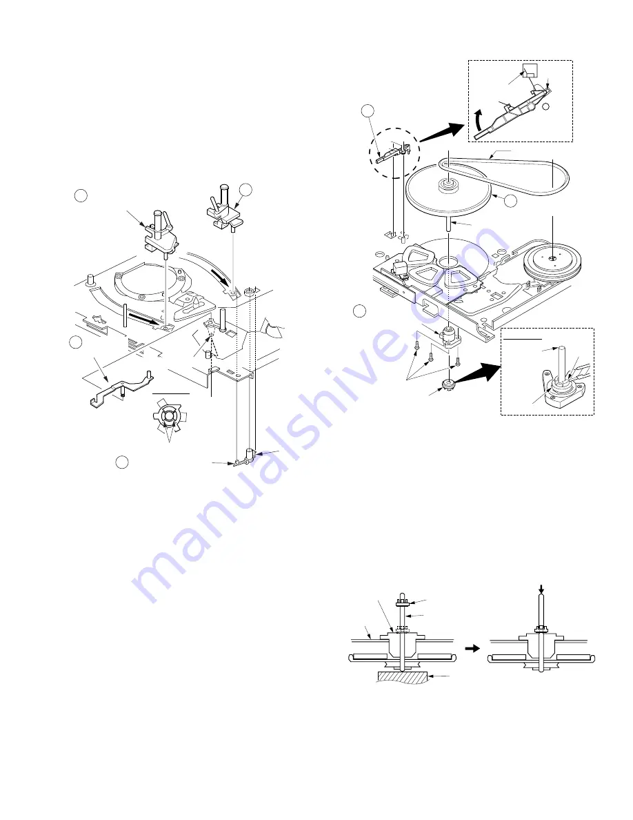
1. Remove the S Brake Arm Unit while releasing 2 Locking
Tabs (I).
2. Remove the Main Lever Guide while releasing Locking Tab
(J).
3. Slide the Loading Post Base -S and T Units to the end of the
guide slots to remove.
Fig. J10
Reassembly Notes
1. Adjustment of Loading Post Base -S Unit and Loading
Post Base -T Unit
1) After installing, perform the "P2 and P3 Post Height
Adjustment" procedures and "Tape Interchangeability
Adjustment" procedures.
Capstan Rotor Unit, Capstan Holder Unit,
and SS Brake Arm Unit
Disassembly Procedure
1. Remove the Capstan Belt.
2. Cut the Stopper with a cutter to remove.
3. Pull up on the Capstan Rotor Unit.
4. Remove 3 Screws (B). Then remove the Capstan Holder
Unit.
5. Unhook Spring (B).
6. Turn the SS Brake Arm Unit so that the Tab (A) lines up with
the niche. Then, remove the SS Brake Arm Unit.
Fig. J11-1
Reassembly Notes
1. Installation of Capstan Rotor Unit
1) Insert the Capstan Rotor Unit Shaft into the hole of the
Capstan Holder Unit.
2) Place a support under the Capstan Rotor Unit shaft.
Install the Stopper. Be careful not to scratch the shaft or
Capstan Holder Unit.
3) Remove the support. Press the top end of the shaft
down so that the Stopper is properly positioned.
You should be able to move the shaft up and down
slightly when properly positioned.
Fig. J11-2
2. Capstan Rotor Kit
Capstan Rotor Unit, Capstan Holder Unit, and Stopper are
supplied as a Capstan Rotor Kit only. (Kit No. VXPS0382K2)
They are not reusable. Install all new parts.
Because even invisible scratches on the Capstan Rotor
Unit shaft and the Capstan Holder Unit, made when cutting
the Stopper, could cause tape path instability.
Summary of Contents for PV-M1348
Page 5: ...1 3 ...
Page 6: ...1 4 ...
Page 7: ...1 5 ...
Page 8: ...1 6 ...
Page 60: ......
Page 61: ......
Page 62: ......
Page 63: ......
Page 64: ......
Page 65: ......
Page 66: ......
Page 67: ......
Page 68: ......
Page 69: ......
Page 70: ......
Page 71: ......
Page 72: ......
Page 73: ......
Page 74: ......
Page 75: ......
Page 76: ......
Page 77: ......
Page 78: ......
Page 79: ......
Page 80: ......
Page 81: ......
Page 82: ......
Page 83: ......
Page 84: ......
Page 85: ......
Page 86: ......
Page 87: ......
Page 88: ......
Page 89: ......
Page 90: ......
Page 91: ......
Page 92: ......
Page 93: ......
Page 94: ......
Page 95: ......
Page 96: ......
Page 97: ......
Page 98: ......
Page 99: ......
Page 100: ......
Page 101: ......
Page 102: ......
Page 130: ...Printed in Japan ...


