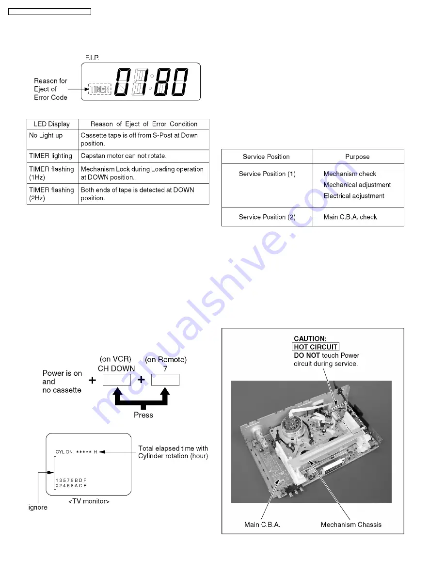
4.1.3.1. Reason of Ejection
When an error code is 80, the reason of ejection is displayed
on the Light Emitting Diode (LED) display of “TIMER”.
Fig. 1-6
Fig. 1-7
4.1.4. Memory and Clear of Fault Code
·
Error code is memorized on EEPROM (IC6004) (latest Error
code only).
·
Error code is cleared by power on operation after a self-
diagnostic display or Memory all clear.
4.2. USAGE SCREEN MODE
Function displayed on the TV monitor:
·
the total elapsed “Cylinder rotation” time (in hours)
1. With power turned on and no cassette, press CH DOWN
button on VCR and 7 key on remote controller together.
(The USAGE SCREEN will be displayed on the TV
Monitor.)
Fig. 2-1
Note:
1. After replacing the Cylinder Unit, press COUNTER
RESET button on remote controller in this mode. Total
elapsed “Cylinder rotation” time (in hours) will be cleared
to 0.
2. To release from Usage Screen Mode, press any
operation button on remote controller or insert a
cassette tape in this mode. The VCR will return to
normal operation mode.
4.3. EEPROM IC (IC6004), MAIN
C.B.A. REPLACEMENT NOTE
After replacing EEPROM IC (IC6004) or Main C.B.A., be sure
to perform the "PG SHIFTER ADJUSTMENT".
4.4. SERVICE POSITION
CAUTION:
HOT CIRCUIT
(Primary circuit) exists on the Main C.B.A.
Use extreme care to prevent accidental shock when
servicing.
NOTE:
When carring out loading of the cassette tape, if light is
strong, a tape may not carry out loading.
Please shade a Mechanism Unit top or weaken lighting.
4.4.1. Service Position (1)
Fig. 4-1
8
PV-V4525S / PV-V4535S-K / PV-455S-K
Summary of Contents for PV-V4525S
Page 13: ...Fig D2 13 PV V4525S PV V4535S K PV 455S K...
Page 30: ...PV V4525S PV V4535S K PV 455S K 30...
Page 32: ...PV V4525S PV V4535S K PV 455S K 32...
Page 37: ...10 EXPLODED VIEWS 10 1 MECHANISM SECTION 37 PV V4525S PV V4535S K PV 455S K...
Page 38: ...10 2 CHASSIS FRAME AND CASING PARTS SECTION 38 PV V4525S PV V4535S K PV 455S K...
Page 39: ...10 3 PACKING PARTS AND ACCESSORIES SECTION 39 PV V4525S PV V4535S K PV 455S K...


