13
PV-DF204/PV-DF2004/PV-DF2004-K/PV-DF274/PV-DF2704/PV-DF2704-K
Replace the IC8001 on the DVD Main C.B.A.
NG
OK
(DVD Playback)
(CD Playback)
DVD Mechanism Unit is defective.
Replace the DVD Mechanism Unit.
NG
NG
OK
OK
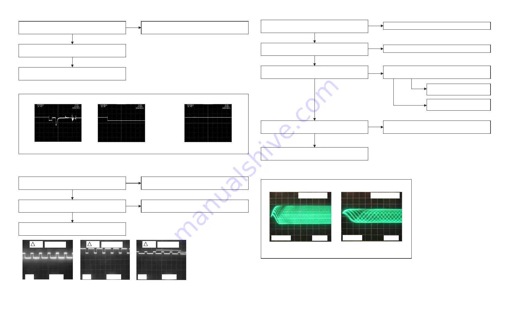
TP8801
TP8802
TP8814
Check the voltage at TP8923 on the DVD Main C.B.A.
Is it +2.2 V ?
Pickup Operation Problem
RF Signal at TP8916
IC8801 on the DVD Main C.B.A. is defective.
Replace IC8801 on the DVD Main C.B.A.
IC8001 on the DVD Main C.B.A. is defective.
Replace IC8001 on the DVD Main C.B.A.
If the Message "PLEASE CHECK THE DISC, AND
FOR STAINS OR SCRATCHES ON DISC" appears.
Check the signal at TP8801 and TP8802 on the DVD
Main C.B.A.
Check the signal at TP8814 on the DVD Main C.B.A.
Traverse Operation Problem
IC8001 on the DVD Main C.B.A. is defective.
Replace IC8001 on the DVD Main C.B.A.
1 V
2 V
V1 0.5 Vp-p
V1 2.0 Vp-p
V1 1.8 Vp-p
5 ms
5 ms
2 V
5 ms
NG
Confirm Wave form at TP8916
from normal DVD Movie or CD.
DVD Mechanism Unit is defective.
Replace the DVD Mechanism Unit.
50 ns
200 mV
50 ns
200 mV
600 mVp-p
400 mVp-p
Check the voltage at TP8906 on the DVD Main C.B.A.
Is it +5.0 V ?
Replace the Q8905 and Q8906
on the DVD Main C.B.A.
Replace the IC8001 on the
DVD Main C.B.A.
NG
OK
NG
OK
Note
: Check the voltage during 10 to 20 seconds as soon as disc has been inserted.
OK
Repair the around circuit of "5V-FEP" line.
NG
Check the voltage at TP8903 on the DVD Main C.B.A.
Is it +5.0 V ?
Check the voltage at TP8925 on the DVD Main C.B.A.
Is it +2.0 V ?
Spindle Motor Operation Problem
DVD Mechanism Unit is defective.
Replace the DVD Mechanism Unit.
IC8001 on the DVD Main C.B.A. is defective.
Replace IC8001 on the DVD Main C.B.A.
Replace IC8801 on the DVD Main C.B.A.
NG
Check the signal at TP8808 (SPIN) on the DVD Main
C.B.A.
OK
Still NG
Signal at TP8808
(Disc Spinning)
OK
OK
(No Disc Spinning)
OR
Note
: Check the signal at TP8808 as soon as disc has been inserted. Otherwise, following waveform can not be monitored.
NG
500 mV
1 s
500 mV
1 s
500 mV
1 s
TROUBLESHOOTING HINTS
Summary of Contents for PVDF204 - DVD/VCR/TV COM
Page 11: ...Fig 1 5 11 ...
Page 12: ...Fig 1 6 12 ...
Page 25: ...Fig D2 25 ...
Page 26: ...Fig D3 26 ...
Page 27: ...Fig D4 27 ...
Page 28: ...6 1 1 1 Notes in chart 1 Removal of VCR DVD Ass y Fig D5 28 ...
Page 48: ...7 4 TEST POINTS AND CONTROL LOCATION 48 ...
Page 51: ...11 2 DVD SECTION 51 ...
Page 52: ...11 3 CHASSIS FRAME SECTION 1 Model A B C D E F 52 ...
Page 53: ...11 4 CHASSIS FRAME SECTION 2 53 ...
Page 54: ...11 5 CHASSIS FRAME SECTION 3 54 ...
Page 55: ...11 6 PACKING PARTS AND ACCESORIES SECTION 55 ...

