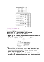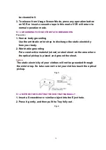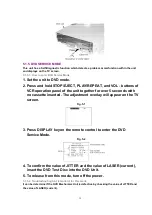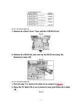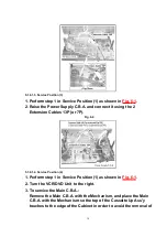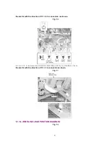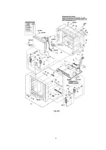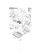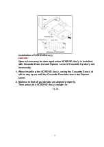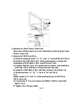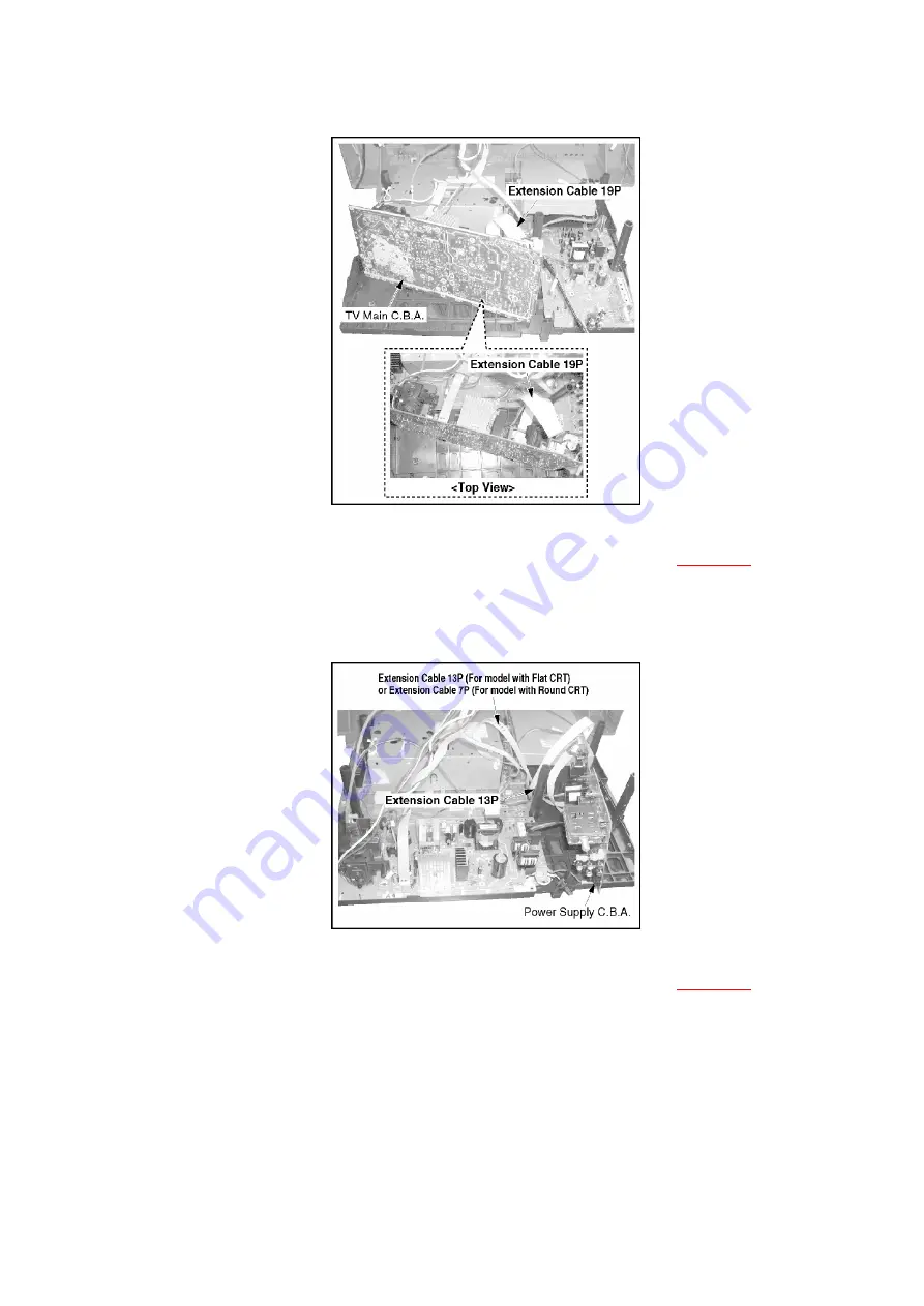
5.1.6.1.3. Service Position (3)
1. Perform step 1 in Service Position (1) as shown in
Fig. 6-1
.
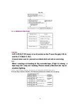
2. Raise the Power Supply C.B.A. and connect it using the 2
Extension Cables 13P (or 7P).
Fig. 6-4
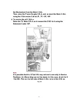
5.1.6.1.4. Service Position (4)
1. Perform step 1 in Service Position (1) as shown in
Fig. 6-1
.
2. Turn the VCR/DVD Unit to the right.
3. To service the Main C.B.A.:
Remove the Main C.B.A. with the Mechanism, and place the Main
C.B.A. with the Mechanism so the top of the Cassette Up Ass'y
touches to the edge of the Cabinet in order to avoid the removal of
18
Summary of Contents for PVDF204 - DVD/VCR/TV COM
Page 11: ...Fig 1 5 11 ...
Page 12: ...Fig 1 6 12 ...
Page 25: ...Fig D2 25 ...
Page 26: ...Fig D3 26 ...
Page 27: ...Fig D4 27 ...
Page 28: ...6 1 1 1 Notes in chart 1 Removal of VCR DVD Ass y Fig D5 28 ...
Page 48: ...7 4 TEST POINTS AND CONTROL LOCATION 48 ...
Page 51: ...11 2 DVD SECTION 51 ...
Page 52: ...11 3 CHASSIS FRAME SECTION 1 Model A B C D E F 52 ...
Page 53: ...11 4 CHASSIS FRAME SECTION 2 53 ...
Page 54: ...11 5 CHASSIS FRAME SECTION 3 54 ...
Page 55: ...11 6 PACKING PARTS AND ACCESORIES SECTION 55 ...

