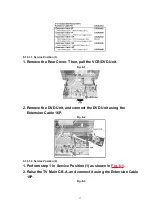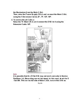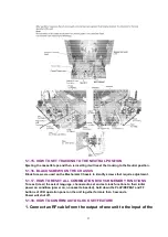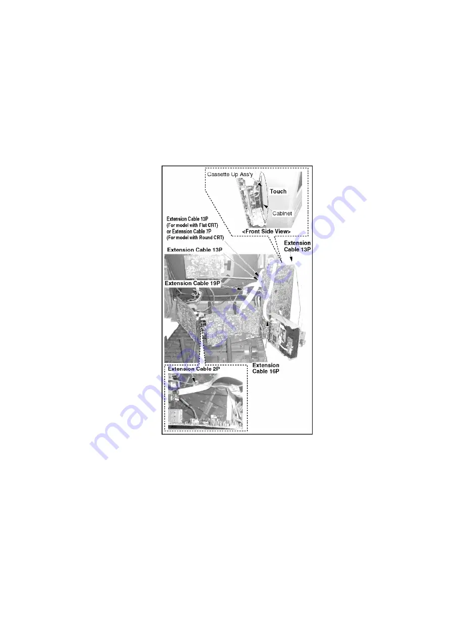
the Mechanism from the Main C.B.A.
Then, raise the Power Supply C.B.A. and connect the Main C.B.A.
using the 5 Extension Cables 2P, 7P, 13P, 19P.
4. To service the all C.B.A.s:
Raise the TV Main C.B.A. and connect the DVD Unit using the
Extension Cable 16P.
Fig. 6-5
Note:
It is possible that the S-Tab SW. may not work correctly in Service
Positions (4). (Recording can not be done). In this case, short the S
-Tab SW. Pins on the foil side of Main C.B.A. to turn this SW. on.
Fig. 6-6
19
Summary of Contents for PVDF204 - DVD/VCR/TV COM
Page 11: ...Fig 1 5 11 ...
Page 12: ...Fig 1 6 12 ...
Page 25: ...Fig D2 25 ...
Page 26: ...Fig D3 26 ...
Page 27: ...Fig D4 27 ...
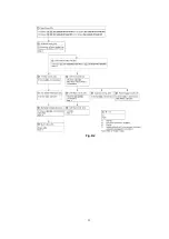
Page 28: ...6 1 1 1 Notes in chart 1 Removal of VCR DVD Ass y Fig D5 28 ...
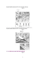
Page 48: ...7 4 TEST POINTS AND CONTROL LOCATION 48 ...
Page 51: ...11 2 DVD SECTION 51 ...
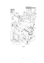
Page 52: ...11 3 CHASSIS FRAME SECTION 1 Model A B C D E F 52 ...
Page 53: ...11 4 CHASSIS FRAME SECTION 2 53 ...
Page 54: ...11 5 CHASSIS FRAME SECTION 3 54 ...
Page 55: ...11 6 PACKING PARTS AND ACCESORIES SECTION 55 ...

