servicing of Combination DVD VCR whose chassis is not isolated
from the AC power line. Use a transformer of adequate power
rating as this protects the technician from accidents resultingin
personal injury from electrical shocks. It will also protect
Combination DVD VCR from being damaged by accidental
shorting that may occur during servicing.
3. When servicing, observe the original lead dress, especially the
lead dress in the high voltage circuits. If a short circuit is found,
replace all parts which have been overheated or damaged by the
short circuit.
4. After servicing, see to it that all the protective devices such as
insulation barriers, insulation papers, shield, and isolation R-C
combinations are properly installed.
5. Before turning the receiver on, measure the resistance between B+
line and chassis ground. Connect (-) side of an ohmmeter to the B
+ lines, and (+) side to chassis ground. Each line should have
more resistance than specified,as follows :
B+ Line
Minimum Resistance
130 V
110 (Cold chassis ground)
28 V
180 (Cold chassis ground)
220 V
1 k (Cold chassis ground)
6. When the TV set is not used for a long period of time, unplug the
power cord from the AC outlet.
7. Potentials, as high as 33.0 kV (For model with 20 inch CRT), 32.0
kV (For model with Round 27 inch CRT), 33.0 kV (For model with
Flat 27 inch CRT) are present when this TV set is in operation.
Operation of the TV set without the rear cover involvesthe danger
of a shock hazard from the TV set power supply. Servicing should
not be attempted by anyone who is not thoroughly familiar with the
precautions necessary when working on high voltage equipment.
3
Summary of Contents for PVDF204 - DVD/VCR/TV COM
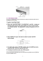
Page 11: ...Fig 1 5 11 ...
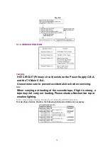
Page 12: ...Fig 1 6 12 ...
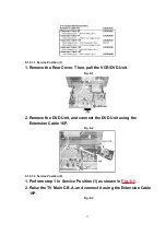
Page 25: ...Fig D2 25 ...
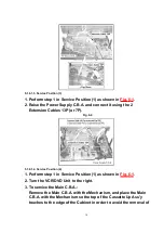
Page 26: ...Fig D3 26 ...
Page 27: ...Fig D4 27 ...
Page 28: ...6 1 1 1 Notes in chart 1 Removal of VCR DVD Ass y Fig D5 28 ...
Page 48: ...7 4 TEST POINTS AND CONTROL LOCATION 48 ...
Page 51: ...11 2 DVD SECTION 51 ...
Page 52: ...11 3 CHASSIS FRAME SECTION 1 Model A B C D E F 52 ...
Page 53: ...11 4 CHASSIS FRAME SECTION 2 53 ...
Page 54: ...11 5 CHASSIS FRAME SECTION 3 54 ...
Page 55: ...11 6 PACKING PARTS AND ACCESORIES SECTION 55 ...


