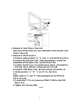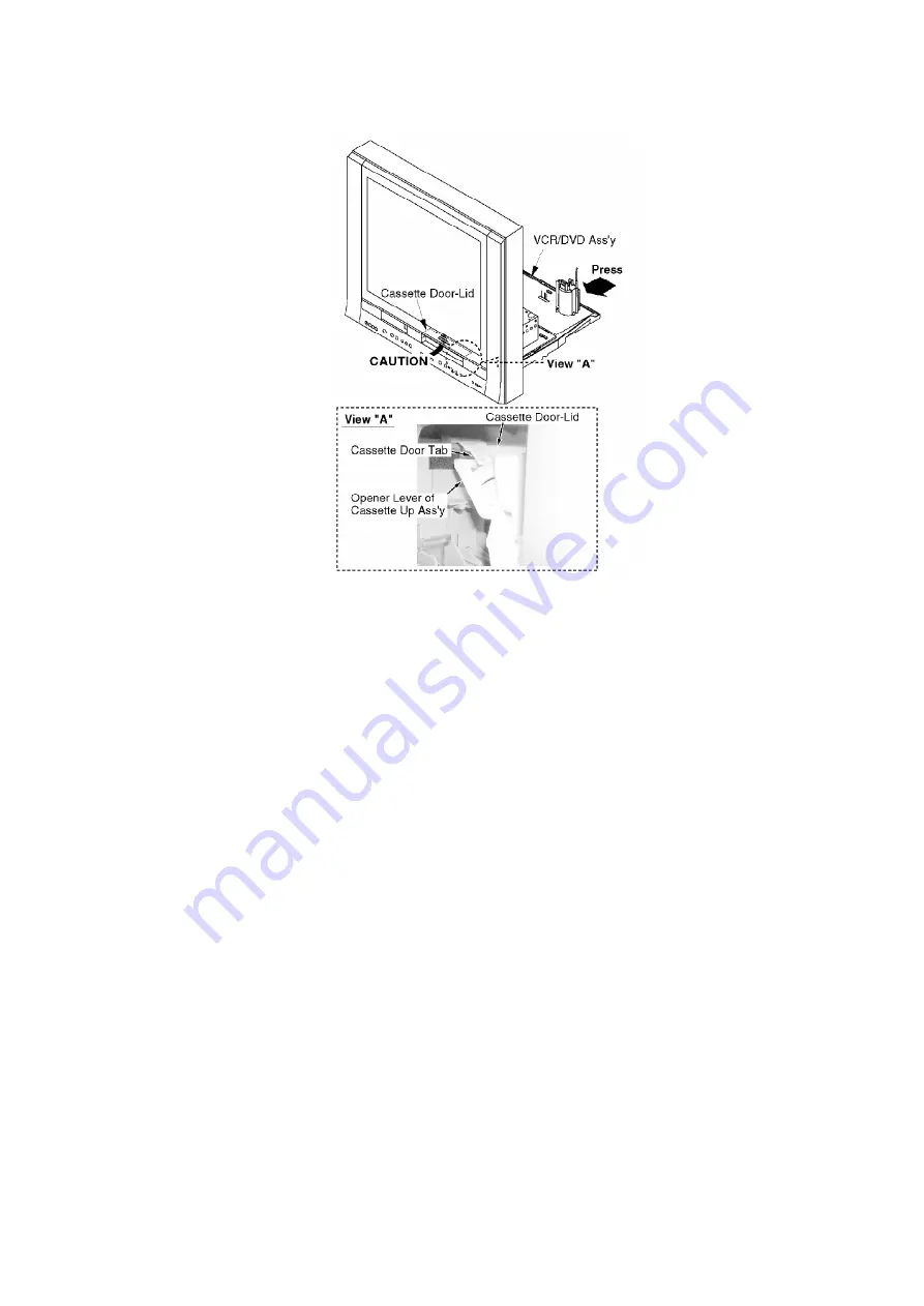
2. Removal of Color Picture Tube Unit
Place the Unit face down on a soft cloth before removing the Color
Picture Tube Unit.
3. Removal of DVD Sub C.B.A.
A. Remove solder portions "a," "b," and "c" on the DVD Sub C.B.A.
B. Remove the DVD Sub C.B.A. while releasing the Locking Tab.
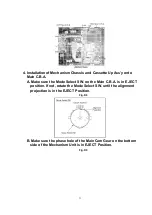
Installation of DVD Main C.B.A. and DVD Sub C.B.A.
A. Confirm that the Lever A is positioned as shown, and install the
DVD Sub C.B.A. with the Locking Tab and 2 bosses.
B. Install the DVD Main C.B.A. with the Locking Tab and the rib.
C. Solder portions "a," "b," "c" and "d" on the C.B.A.
Note:
Solder portions "a" and "b" while pushing down the DVD Sub
C.B.A. securely.
D. Connect the F.F.C.s to Connectors P8901, P8801 on the DVD
Main C.B.A.
E. Tighten the 2 Screws (508).
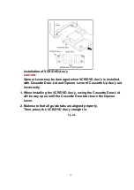
Fig. D7
30
Summary of Contents for PVDF204 - DVD/VCR/TV COM
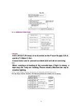
Page 11: ...Fig 1 5 11 ...
Page 12: ...Fig 1 6 12 ...
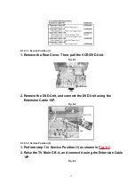
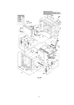
Page 25: ...Fig D2 25 ...
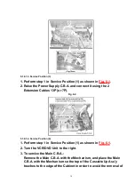
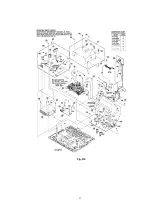
Page 26: ...Fig D3 26 ...
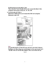
Page 27: ...Fig D4 27 ...
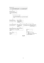
Page 28: ...6 1 1 1 Notes in chart 1 Removal of VCR DVD Ass y Fig D5 28 ...
Page 48: ...7 4 TEST POINTS AND CONTROL LOCATION 48 ...
Page 51: ...11 2 DVD SECTION 51 ...
Page 52: ...11 3 CHASSIS FRAME SECTION 1 Model A B C D E F 52 ...
Page 53: ...11 4 CHASSIS FRAME SECTION 2 53 ...
Page 54: ...11 5 CHASSIS FRAME SECTION 3 54 ...
Page 55: ...11 6 PACKING PARTS AND ACCESORIES SECTION 55 ...

