2. The Mechanical Chassis Sub Ass’y (Ref. No. 4) consists of all the
mechanical parts except the Cylinder Unit (Ref. No. 1), and the
Cassette Up Ass’y (Ref. No. 51) and Cleaner Arm Unit (Ref. No.3).
After replacing the Mechanical Chassis Sub Ass’y, be sure to
perform “TAPE INTERCHANGEABILITY ADJUSTMENT” in Service
Manual for R4-Mechanism - Chassis - for - PV-Model (Order No.
MKE0401000C1).
3. The Infrared Remote Control Unit (Ref. No. 123) replacement part
is available as a complete assembly unit only. Do not try to
disassemble the Infrared Remote Control Unit. However, the
battery cover is available separately as a replacement part.
4. When replacing the DVD Frame (Ref. No. 317), be sure to place the
Rating Label (Ref. No. 318) on it.
5. When replacing the DVD Mechanism Unit (Ref. No. 242) or the DVD
Frame (Ref. No. 317), be sure to place the Cabinet Label (Ref. No.
253) on it.
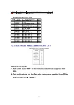
12.1.3. Electrical Replacement Notes
1. Unless otherwise specified;
All resistors are in , K = 1,000 , M = 1,000 k .
2. Abbreviation
RTL:
Retention Time Limited
This indicates that the retention time is limited for this item. After
the discontinuation of this item in production, it will no longer be
available.
NR:
Non Repairable Board Ass'y
MGF CHIP:
Metal Glaze Film Chip
C CHIP:
Ceramic Chip
COMPLX CMP:
Complex Component
58
Summary of Contents for PVDF204 - DVD/VCR/TV COM
Page 11: ...Fig 1 5 11 ...
Page 12: ...Fig 1 6 12 ...
Page 25: ...Fig D2 25 ...
Page 26: ...Fig D3 26 ...
Page 27: ...Fig D4 27 ...
Page 28: ...6 1 1 1 Notes in chart 1 Removal of VCR DVD Ass y Fig D5 28 ...
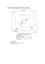
Page 48: ...7 4 TEST POINTS AND CONTROL LOCATION 48 ...
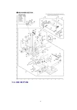
Page 51: ...11 2 DVD SECTION 51 ...
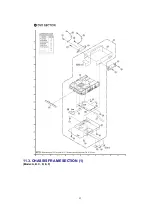
Page 52: ...11 3 CHASSIS FRAME SECTION 1 Model A B C D E F 52 ...
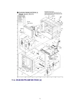
Page 53: ...11 4 CHASSIS FRAME SECTION 2 53 ...
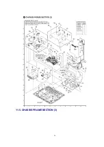
Page 54: ...11 5 CHASSIS FRAME SECTION 3 54 ...
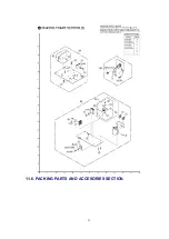
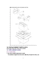
Page 55: ...11 6 PACKING PARTS AND ACCESORIES SECTION 55 ...

