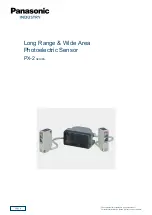
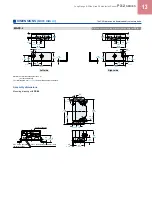
background image

2022.

6

Long Range & Wide Area

Photoelectric Sensor

PX-2

 SERIES

*


The contents of this catalog are as of 

October 2017

.

For the latest information, please visit our company website.

Summary of Contents for PX-2 Series

Page 1: ...2022 6 Long Range Wide Area Photoelectric Sensor PX 2SERIES The contents of this catalog are as of October 2017 For the latest information please visit our company website ...

Page 2: ... has a long sensing range of 5 m 16 404 ft Even on a high speed AGV it can detect an object quite early so that slowing down and stopping are smooth Automatic interference prevention function One PX 2 sensor can simultaneously receive beams from 25 Nos of other PX 2 sensors without resulting in any interference Even if AGVs are facing each other the PX 2 sensor on one AGV reliably detects the othe...

Page 3: ... PX 2 Main sensor mounting bracket MS NX5 1 Auxiliary sensor mounting bracket Two bracket set Four M4 length 8 mm 0 315 in screws with washers are attached Two M4 length 25 mm 0 984 in screws with washers and two M4 nuts are attached OPTIONS Designation Model No Description Auxiliary sensor mounting bracket MS NX5 2 Foot biangled mounting bracket Sensor protection bracket MS NX5 3 Back angled moun...

Page 4: ...erence prevention function Optical interference from up to 25 units is prevented Environmental resistance Pollution degree 3 Industrial environment Protection IP65 IEC Ambient temperature 10 to 55 C 14 to 131 F No dew condensation or icing allowed Storage 20 to 70 C 4 to 158 F Ambient humidity 35 to 85 RH Storage 35 to 85 RH Ambient illuminance Incandescent light 3 000 ℓx or less at the light rece...

Page 5: ...ditions used were an ambient temperature of 20 C 68 F 2 The auxiliary sensor cannot be used as a stand alone unit 3 The sensing range is specified for white non glossy paper 300 300 mm 11 811 11 811 in as the object Specifications other than the above are identical with the main sensor I O CIRCUIT AND WIRING DIAGRAMS PX 24ES PX 23ES I O circuit diagram Wiring diagram 1 Non voltage contact or NPN o...

Page 6: ... 1 area ineffective input Pink Violet Sleep input Pink Gray External sensitivity adjustment input Users circuit Internal circuit 0 to 5 V DC Sensor circuit Input impedance 1 kΩ approx Violet Auxiliary right OUT 1 area ineffective input 10 to 31 V DC For auxiliary sensor connection Load Load Load Brown Blue White Black White Black Violet Violet Black Pink Gray Pink Violet 1 0 to 5 V DC 10 to 31 V D...

Page 7: ... 562 Excess gain 50 PX SB1 PX 21 PX 23ES PX 22 PX 24 PX 24ES Setting distance L m ft PX 26 PX 22 PX 24 PX 24ES Sensing fields Correlation between external sensitivity adjustment input voltage and sensing range Excluding PX 22 All areas effective Horizontal C area effective Horizontal All areas effective Vertical Correlation between sensitivity adjuster and sensing range OUT1 OUT2 area Adjacent rig...

Page 8: ...Max 300 300 mm 11 811 11 811 in White non glossy paper Sensing range L mm in Measurement method of the adjacent right OUT1 area same as the adjacent left OUT1 area PX 26 Sensing fields Correlation between external sensitivity adjustment input voltage and sensing range Horizontal All areas effective Note Vertical All areas effective Note Correlation between sensitivity adjuster and sensing range OU...

Page 9: ... the local and national regulations of the country where this sensor is used CAUTION Fail safe measures This sensor is meant for proximity detection and does not possess control functions for safety maintenance If fail safe measures are required consider their incorporation in the total system Further do not connect the sensor output directly to a stopping mechanism brake CAUTION Periodical mainte...

Page 10: ...Sensitivity adjuster OUT 2 area Sensing area sensitivity adjuster Adjacent left OUT 1 area OUT 1 area OUT 2 area Adjacent right OUT 1 area OUT 1 area Adjacent right OUT 1 area Adjacent left OUT 1 area Sensing area selection switch Note 1 Left area Selection of main sensor sensing areas OUT 1 OUT 2 Left area Right area center area OFF R L Effective OFF R L Ineffective Right area Output operation mo...

Page 11: ...ivity cannot be set to close range even after adjusting the emitter volume then an aux sensor might be receiving the light from the main sensor If that is the case adjust sensitivity with the emitter volume and the receiver volume For details see the instruction manual that comes with the product Connection with the main sensor Connect the main sensor connector attached cable to the aux sensor con...

Page 12: ...er incorporated Emission adjuster incorporated The CAD data can be downloaded from our website PX 2 Main sensor Note PX 22 and PX 21 do not have this cable 28 5 1 122 20 0 787 62 2 441 5 0 197 23 5 0 925 38 5 1 516 45 45 63 2 480 73 2 874 83 3 268 41 5 1 634 22 0 866 12 0 472 4 5 0 177 43 1 693 40 5 1 594 2 5 0 098 9 0 354 15 0 591 21 5 0 846 Center of sensing 11 0 433 4 M4 threads 4 deep 2 ø4 6 ø...

Page 13: ... Uni chrome plated Four M4 length 8 mm 0 315 in screws with washers are attached 1 7 0 067 9 1 0 358 9 4 0 370 31 9 1 256 16 5 0 650 0 3 0 012 5 0 197 15 0 591 11 5 0 453 20 0 787 47 1 850 21 0 827 t 2 t 0 079 4 8 0 189 4 5 0 177 12 0 472 Left side Right side t 2 t 0 079 28 5 1 122 6 5 0 256 47 1 850 21 0 827 50 1 969 17 0 669 20 0 787 10 5 0 413 104 4 094 116 4 567 52 2 047 4 8 0 189 9 2 0 362 Ce...

Page 14: ...ni chrome plated Two M4 length 25 mm 0 984 in screws with washers and two M4 nuts are attached Material Cold rolled carbon steel SPCC Uni chrome plated Two M4 length 25 mm 0 984 in screws with washers and two M4 nuts are attached Auxiliary sensor mounting bracket Optional 6 0 236 25 0 984 70 0 3 2 756 0 012 t 2 t 0 079 6 0 236 14 0 551 17 0 669 29 1 142 10 0 394 8 0 315 40 1 575 37 1 457 6 0 236 6...

Page 15: ...e have obtained some intellectual properties such as patent rights with respect to such applications or that the described applications may not infringe any intellectual property rights such as patent rights of a third party Printed in Japan Industrial Device Business Division 7 1 1 Morofuku Daito shi Osaka 574 0044 Japan industrial panasonic com ac e ⓒ Panasonic Industry Co Ltd Specifications are ...

Reviews: