


Long Range & Wide Area Photoelectric Sensor
PX-2
SERIES
5
*1
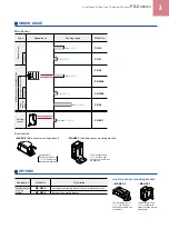
For auxiliary
sensor connection
0 to +5 V DC
Load
Load
Load
Brown
Blue
White
Pink
Pink / Black
Pink / White
Pink / Violet
Violet
Violet / Black
Pink / Gray
Black / White
Black
+ -
+
-
10 to 31 V DC
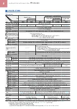
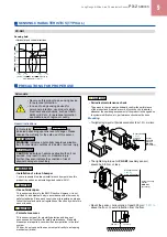
SPECIFICATIONS
Auxiliary sensor (Note 2)
Item
Model No.
PX-SB1
CE marking directive compliance
EMC Directive, RoHS Directive
Applicable main sensor
PX-24
,
PX-24ES
,
PX-23ES
or
PX-26
Connectable units
Up to two
PX-SB1
’s can be connected to one main sensor.
Sensing range (Note 3)
700 mm
27.559 in
Supply voltage
Supplied from the main sensor
Current consumption
Current consumption of the main sensor increases by 30 mA approx. per auxiliary sensor.
Output
OR circuit with the main sensor’s OUT 1
Operation indicator
Red LED (lights up when the beam is received)
Sensitivity adjuster
Continuously variable adjuster
Emitting element
Infrared LED (modulated)
Material
Polycarbonate
Cable
0.3 mm
2
5-core cabtyre cable, 2 m
6.562 ft
long
Cable extension
Extension up to total 10 m
32.808 ft
is possible with 0.3 mm
2
, or more, cable.
Weight
Net weight: 130 g approx., Gross weight: 240 g approx
Accessories
MS-NX5-1
(Auxiliary sensor mounting bracket): 1 set, Adjusting screwdriver: 1 pc.
Notes: 1) Where measurement conditions have not been specified precisely, the conditions used were an ambient temperature of +20 °C
+68 °F
.
2) The auxiliary sensor cannot be used as a stand-alone unit.
3) The sensing range is specified for white non-glossy paper (300 × 300 mm
11.811 × 11.811 in
) as the object.
Specifications other than the above are identical with the main sensor.
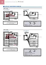
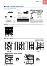
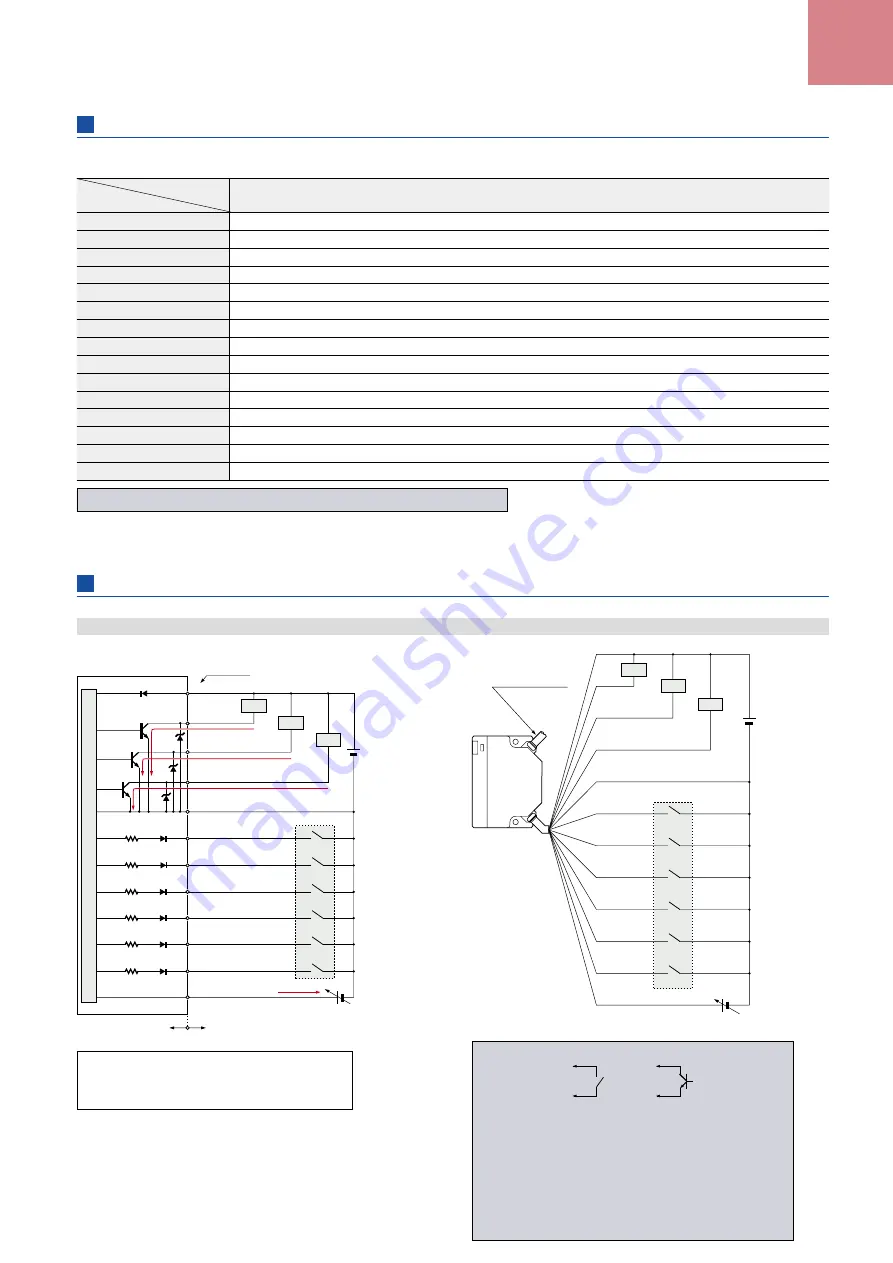
I/O CIRCUIT AND WIRING DIAGRAMS
PX-24ES PX-23ES
I/O circuit diagram
Wiring diagram
* 1
Non-voltage contact or NPN open-collector transistor
or
• Area selection input
Low (0 to 1 V): Depends on the logic combination
(Refer to p.
10
)
High (4.5 to 31 V, or open): Depends on the logic combination
(Refer to p.
10
)
• Auxiliary area ineffective input
Low (0 to 1 V): Area ineffective
High (4.5 to 31 V, or open): Area effective
• Sleep input
Low (0 to 1 V): Sleep condition
High [(supply voltage – 1 V) to 31 V, or open]: Operating condition
Users’ circuit
Internal circuit
Sensor circuit
D
(Brown) +V
100 mA max.
Load
Z
D2
Z
D1
Z
D3
(Blue) 0 V
0 to +5 V DC
+ -
100 mA max.
100 mA max.
6 mA max.
Color code
*1
Tr
3
Tr
2
Tr
1
(White) OUT 2
(Pink)
Area Selection Input 1
(Pink / Black)
Area Selection Input 2
(Pink / White)
Area Selection Input 3
(Pink / Violet) Sleep input
(Violet) Auxiliary right OUT 1
area ineffective input
(Violet / Black) Auxiliary left
OUT 1 area ineffective input
(Pink / Gray) External
sensitivity adjustment input
(Black / White) Extraneous light monitor output
(Black) OUT 1
Load
Load
(Input impedance: 1 kΩ approx.)
+
-
10 to 31 V DC
Symbols … D: Reverse supply polarity protection diode
Z
D1
, Z
D2
, Z
D3
: Surge absorption zener diode
Tr
1
, Tr
2
, Tr
3
: NPN output transistor


