Note:
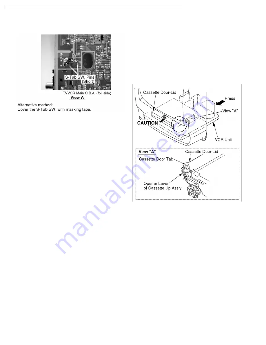
1. When recording in Service Position (2), short the S-Tab
SW. Pins on foil side of TV/VCR Main C.B.A. to turn this
SW. on.
Fig. 2-3
2. When
disassembling/assembling,
refer
to
"CABINET
SECTION"
in
DISASSEMBLY/ASSEMBLY
PROCEDURES.
5.1.3. HOT CIRCUIT
Primary circuit exists on the TV/VCR Main C.B.A.
This circuit is identified as " HOT " on the C.B.A. and in the
Service Manual. Use extreme care to prevent accidental shock
when servicing.
5.1.4. SERVICE MODE
In order to inhibit detection of the Supply & Takeup Photo
Transistors, Reel Sensor, and Cylinder Lock, place a jumper
between TP6001 and GND.
In this mode, Mechanism movement can be confirmed. When
removing Cassette Up Ass'y, it can be confirmed without a
cassette.
To release from this mode, remove the jumper between
TP6001 and GND.
5.1.5. CAUTION FOR INSTALLATION OF
VCR UNIT
CAUTION:
Opener Lever may be damaged when VCR Unit is
installed, with Cassette Door-Lid and Opener Lever of
Cassette Up Ass'y set incorrectly.
Install the VCR Unit as follows:
1. Swing the Cassette Door-Lid all the way open until the
Cassette Door tab clears the Opener Lever.
2. Make sure that all guide tabs are aligned properly. Then,
press the VCR Unit straight in.
Fig. 3
14
PVQ-1310 / PV-C1320 / PV-C1330W / VV-1300 / VV-1310W / PV-C1340 / PV-C1350W / PV-C2010 / PV-C2020 / PV-C2030W / VV-2000 / PV-C2060


