7.3. ELECTRICAL ADJUSTMENT
7.3.1. TEST EQUIPMENT
To do all of these electrical adjustments, the following
equipment is required.
1. Dual-Trace Oscilloscope
Voltage Range: 0.001 V to 50 V/Div.
Frequency Range: DC to 50 MHz
Probes: 10:1, 1:1
2. NTSC Video Pattern Generator
3. DVM (Digital Volt Meter)
4. MTS/SAP Signal Generator
(TV Multi-Channel Sound Modulator (U.S.A.))
5. Frequency Counter
Frequency Range: 0 to 150 MHz
6. Plastic Tip Driver and Non-Metal Driver
7. Isolation Transformer (Variable)
8. VHS Alignment Tape (VFMS0003H6)
9. Degaussing Coil
10. White Pattern Generator
11. Audio Generator
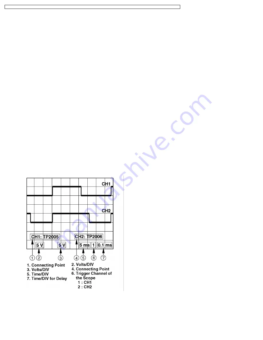
7.3.2. HOW TO READ THE ADJUSTMENT
PROCEDURES
Fig. E1
7.3.3. 115 V ADJUSTMENT
Purpose:
To set the optimum voltage.
Symptom of
Misadjustment:
The picture is dark and unit does not
operate correctly.
Test Point:
TP1203, TP804 (TV/VCR Main C.B.A.)
Adjustment:
R850 (TV/VCR Main C.B.A.)
Specification:
115 VDC±0.2 VDC
Input:
Video Input Jack, Monoscope Pattern
Signal
Mode:
STOP
Equipment:
DVM (Digital Volt Meter)
1. Supply a Monoscope Pattern Signal to the Video Input
Jack.
2. Connect the DVM (Digital Volt Meter) to TP1203 (+) and
TP804 (-) on the TV/VCR Main C.B.A.
3. Adjust R850 (115 V ADJ) so that the voltage is 115
VDC±0.2 VDC.
46
PVQ-1310 / PV-C1320 / PV-C1330W / VV-1300 / VV-1310W / PV-C1340 / PV-C1350W / PV-C2010 / PV-C2020 / PV-C2030W / VV-2000 / PV-C2060


