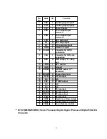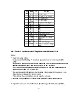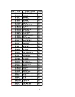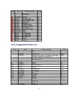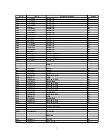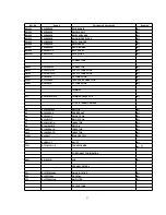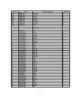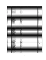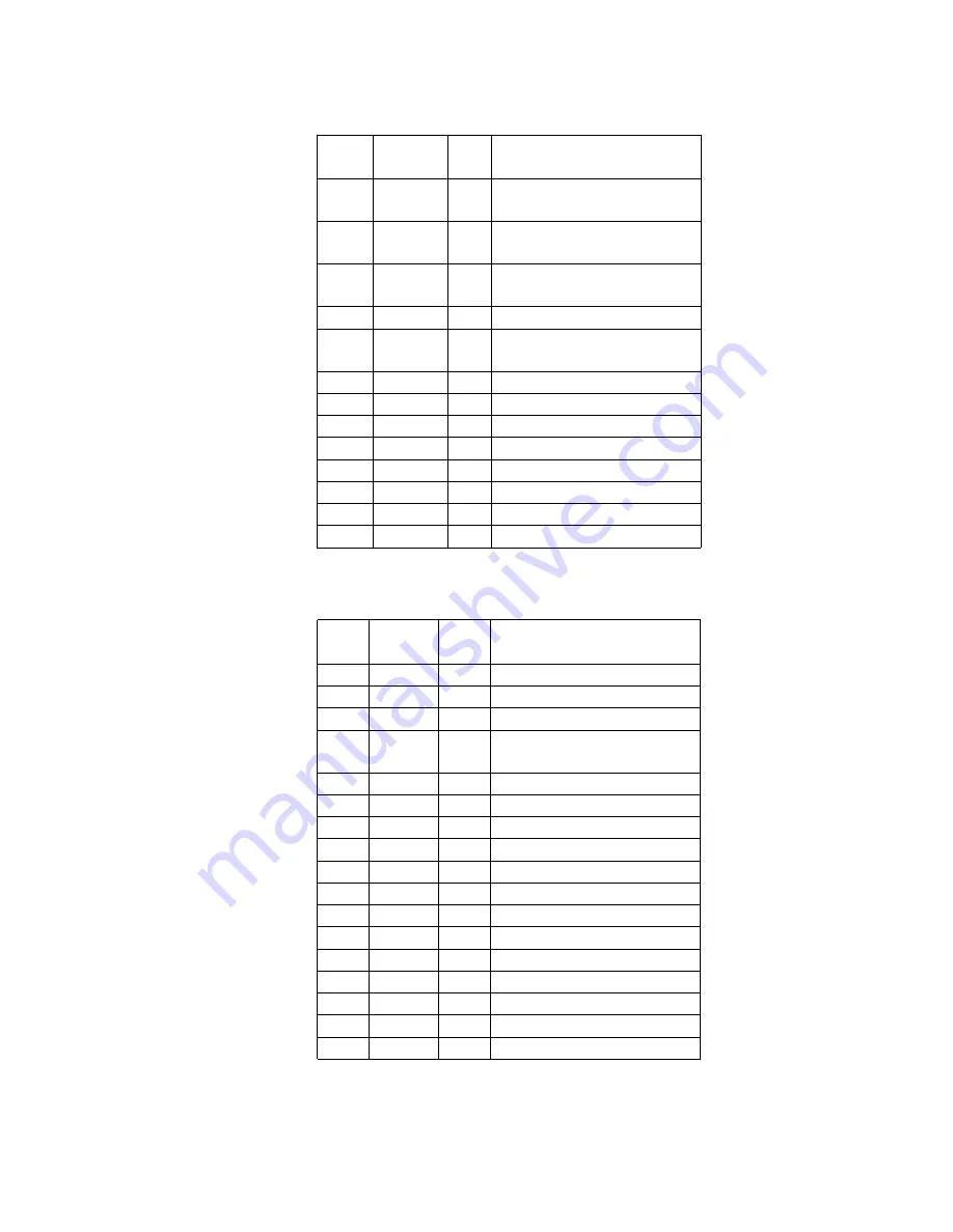
Pin
No.
Mark
I/O
Function
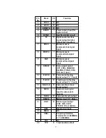
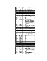
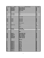
16
D3+
O
Motor driver (3) forward-
action output
17
D4-
O
Motor driver (4) reverse-
action output
18
D4+
O
Motor driver (4) forward-
action output
19
NC
-
N.C.
20
PGND2
-
Ground connectin (2) for
driver
21
PVCC2
I
Power supply (2) for driver
22
NC
-
N.C.
23
VCC
I
Power supply terminal
24
VREF
I
Reference voltage input
25
IN4
I
Motor driver (4) input
26
IN3
I
Motor driver (3) input
27
RSTIN
I
Reset terminal
28
NC
-
N.C.
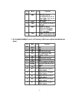
-
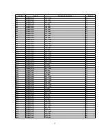
IC801 (M38224M6H104) Microprocessor
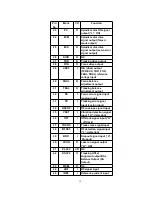
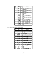
Pin
No.
Mark
I/O
Function
1
VLCD2
-
LCD power source
2
VLCD1
-
LCD power source
3
KEY_1
A-D
Key 1 input
4
REM_CTL
O
Control on/off of remote
sensor
5
REG_2
A-D
Region setting 2
6
REG_1
A-D
Region setting 1
7
R_CTL
O
Region control
8
P.DET
A-D
Power detect input
9
REG_3
I
Region setting 3
10
N.C
-
N.C.
11
CD_SEL
I
CD mode selector input
12
TU_SEL
I
Tuner mode selector input
13
TP_SEL
I
Tape mode selector input
14
REC H
I
Record H input
15
B.P.1
-
N.C.
16
N.C
-
N.C.
17
SEL_IN
I
Function mode selection
42
Summary of Contents for RXD10 - RADIO CASSETTE W/CD
Page 6: ...6 ...
Page 8: ...6 Controls 8 ...
Page 9: ...9 ...
Page 13: ...13 ...
Page 14: ...14 ...
Page 15: ...15 ...
Page 17: ...8 1 2 Checking for CD Servo P C B 17 ...
Page 18: ...Step 9 Remove the FFC wire from CN702 18 ...
Page 19: ...8 2 Main Component Replacement Procedures 8 2 1 Replacement of the Traverse Deck 19 ...
Page 21: ...Note Insert a short pin into the flexible cable for traverse unit 21 ...
Page 22: ...Step 4 Remove the flexible cable CN701 22 ...
Page 26: ...26 ...
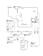
Page 27: ...10 Printed Circuit Board 11 Wiring Connection Diagram 27 ...
Page 28: ...28 ...
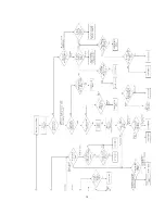
Page 29: ...12 Troubleshooting Guide 29 ...
Page 30: ...30 ...

