


Installation and operation manual
2
S-20~125LM3HPQ
Urban Multi air conditioner
4PW15112-1B
Notes to the installer
■
Read this manual carefully to ensure correct installation. Be
sure to instruct the customer how to properly operate the system
and show him/her the enclosed operation manual.
■
Explain to the customer what system is installed on the site. Be
sure to fill out the appropriate installation specifications in the
chapter "What to do before operation" of the outdoor unit
operation manual.
S
ELECTING
INSTALLATION
SITE
1
Select an installation site where the following conditions are
fulfilled and that meets your customer's approval.
•
Where optimum air distribution can be ensured.
•
Where nothing blocks air passage.
•
Where condensate water can be properly drained.
•
Where the false ceiling is not noticeably on an incline.
•
Where sufficient clearance for maintenance and service can be
ensured.
•
Where piping between indoor and outdoor units is possible within the
allowable limit. (Refer to the installation manual of the outdoor unit.)
•
This is a class A product. In a domestic environment this product
may cause radio interference in which case the user may be
required to take adequate measures.
•
Keep indoor unit, outdoor unit, power supply wiring and
transmission wiring at least 1 meter away from televisions and
radios. This is to prevent image interference and noise in those
electrical appliances.
(Noise may be generated depending on the conditions under
which the electric wave is generated, even if 1 meter is kept.)
2
Ceiling height
This indoor unit may be installed on ceilings up to 3 m in height.
3
Use suspension bolts for installation. Check whether the ceiling
is strong enough to support the weight of the indoor unit. If there
is a risk, reinforce the ceiling before installing the unit.
(The installation pitch is marked on the paper pattern for
installation. Refer to it to check for points requiring reinforcing.)
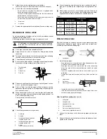
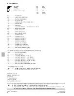
Space required for installation see figure 1.
P
REPARATIONS
BEFORE
INSTALLATION
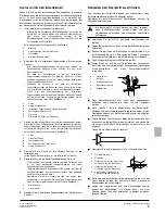
1.
Relation of ceiling opening to unit and suspension bolt position.
(See figure 2)
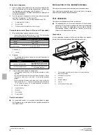
2.
Make the ceiling opening needed for installation where
applicable. (For existing ceilings.)
•
Refer to the paper pattern for installation for the ceiling opening
dimensions.
•
Create the ceiling opening required for installation. From the side
of the opening to the casing outlet, implement the refrigerant and
drain piping and wiring for remote controller (unnecessary for
wireless type) and indoor-outdoor unit casing outlet. Refer to
each piping or wiring section.
•
After making an opening in the ceiling, it may be necessary to
reinforce ceiling beams to keep the ceiling level and to prevent it
from vibrating. Consult the builder for details.
3.
Install the suspension bolts. (use either a W3/8 or M10 size bolt.)
Use anchors for existing ceilings, and a sunken insert, sunken
anchors or other field supplied parts for new ceilings to reinforce the
ceiling in order to bear the weight of the unit. Adjust clearance from
the ceiling before proceeding further.
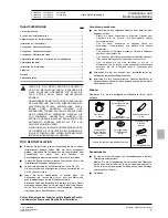
Installation example see figure 3.
I
NDOOR
UNIT
INSTALLATION
When installing optional accessories (except for the decoration
panel), read also the installation manual of the optional accessories.
Depending on the field conditions, it may be easier to install optional
accessories before the indoor unit is installed. However, for existing
ceilings, install fresh air inlet component kit and branch duct before
installing the unit.
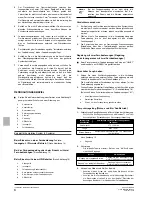
1.
Install the indoor unit temporarily.
•
Attach the hanger bracket to the suspension bolt. Be sure to fix it
securely by using a nut and washer from the upper and lower
sides of the hanger bracket.
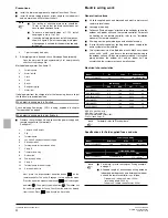
Securing the hanger bracket see figure 4.
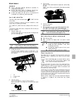
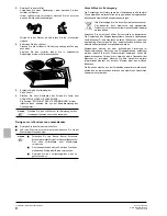
2.
Fix the paper pattern for installation. (For new ceilings only.)
•
The paper pattern for installation corresponds with the measure-
ments of the ceiling opening. Consult the builder for details.
•
The centre of the ceiling opening is indicated on the paper
pattern for installation. The centre of the unit is indicated on the
label attached to the unit and on the paper pattern for installation.
•
After cutting out a slit for the unit in the center of the paper pattern
for installation (supplied with the unit), install it with the 4 supplied
screws.
•
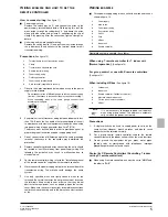
Fold the guide section of the paper pattern for installation and
adjust the height of the unit so that the notch in the guide is at the
position where you expect the ceiling surface to be. See figure 5.
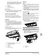
3.
Adjust the height of the unit. (For existing ceilings only.)
Cut out the guide section of the supplied paper pattern for
installation, place on the bottom surface of the unit, and adjust the
height of the unit so that the notch of the guide matches the lower
surface of the ceiling. See figure 6.
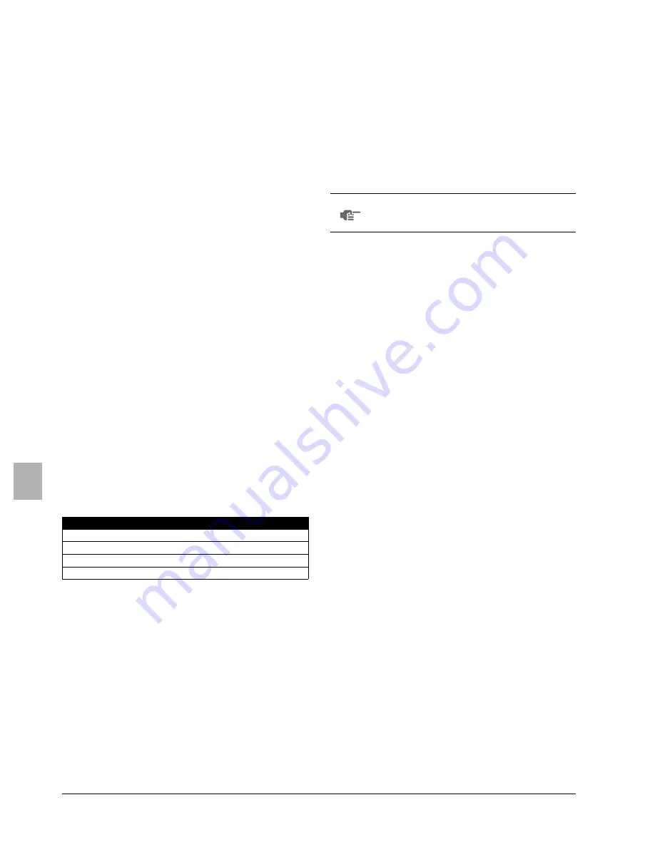
Model
A
B
C
D
S-20~32LM3HPQ
990
820
780
1030
S-40,50LM3HPQ
1205
1035
995
1245
S-63LM3HPQ
1390
1220
1180
1430
S-80,125LM3HPQ
1880
1710
1670
1920
1
Decoration panel
2
Ceiling opening
3
Indoor unit
4
Suspension bolt (x4)
5
Suspension pitch
6
Unit outside dimensions
7
Panel outside dimensions
1
Ceiling slab
2
Anchor
3
Long nut or turn-buckle
4
Suspension bolt
5
False ceiling
NOTE
All the above parts are field supplied.
For other installation than standard installation, contact
your Panasonic dealer for details.
1
Field supplied
2
Washer (supplied with the unit)
3
Hanger bracket
4
Tighten (double nut)
1
Ceiling
2
Lower surface of ceiling
3
Paper pattern for installation (supplied with the unit)
4
Guide section (4 corners)
5
Cut-out section
6
Screws (x4 supplied with the unit)
1
Ceiling
2
Unit body
3
Guide portion
4
Unit height adjustment
5
Lower surface of ceiling
Summary of Contents for S-20LM3HPQ
Page 75: ...4PW15112 1B...


