
OVERVIEW
1
This product is an ultra-small
S-LINK
relay output terminal unit
which permits relay replacement.
SL-TPR4
,
SL-TPR8
Sensor & Wire-saving Link System
S-LINK
Relay Output Terminal Unit
Thank you very much for purchasing Panasonic products. Read
this Instruction Manual carefully and thoroughly for the correct
and optimum use of this product. Kindly keep this manual in a
convenient place for quick reference.
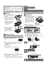
PART DESCRIPTION
2
●
SL-TPR4 / 4 channel relay output type
●
SL-TPR8 / 8 channel relay output type
4-core flat cable 0.6m long
Transmission indicator (Green)
Address setting switch
2-mounting holes for M4 screws
Relay removal key
Output hold setting switch
4-operation indicators (Orange)
Terminal block
DIN rail stopper
Setting switch section
Switch cap removed
condition
output relays
(4
relays
)
PA-N Relay APAN3124
made by Panasonic
Corporation
Output hold setting switch
8-operation indicators (Orange)
Terminal block
DIN rail stopper
4-core flat cable 0.6m long
Transmission indicator (Green)
Address setting switch
2-mounting holes for M4 screws
Relay removal key
Setting switch section
Switch cap removed
condition
output relays
(8
relays
)
PA-N Relay APAN3124
made by Panasonic
Corporation
PRECAUTIONS
3
●
●
●
●
●
●
●
Do not use during the initial transient time (0.5 sec.) after the
power supply is switched on.
If power is supplied from a commercial switching regulator,
ensure that the frame ground (F.G.) terminal of the power
supply is connected to an actual ground.
Do not run the wires together with high-voltage lines or power
lines or put them in the same raceway. This can cause
malfunction due to induction.
A switch cap is fitted on the setting switch section. Remove
the cap at the time of setting. After the setting, make sure to fit
it back.
Use tweezers, etc., having a tip width of approx. 0.8mm to
operate the switches.
This product does not have a dust-proof or water-proof
construction. Do not use it in places having excessive water
vapor, dust, corrosive gas or where it may come in direct
contact with water or chemicals.
Make sure to fit the cover before use.
●
●
Make sure that the power supply is off while wiring.
Switch on the power supply after confirming that the wiring is
correct. If the power supply is switched on when the wiring is
incorrect, there is a danger of malfunction or damage.
SPECIFICATIONS
4
Item
Model No.
Type
4 channel relay output
Supply voltage
24V DC
±
10%
(supplied from the
S-LINK
control unit or separate power supply)
Transmission indicator
Green LED (blinks to indicate the synchronization signal
transmission from the
S-LINK
control unit)
Ambient temperature
0 to +55
℃
(No dew condensation), Storage: -20 to +70
℃
Ambient humidity
35 to 85% RH, Storage: 35 to 85% RH
Cable
0.5mm
2
4-core flat cable 0.6m
Material
Case: PC-ABS resin, Cover: Polycarbonate
DIN rail stopper: POM, Relay removal key: POM
Accessories
Cover: 1 pc., Switch cap: 1 pc., Relay removal key: 1 pc.
Operation indicator
Orange LEDs (lights when the output relay is ON)
Output hold function
Incorporated
Output
(per relay)
Relay contact 1a
・
Nominal switching capacity : 250V 2A AC (resistive load)
30V 2A DC (resistive load)
・
Min. switching capacity : 5V 1mA DC (Note 1)
・
Expected life: 100,000 operations or more
(at rated voltage, switching rate 20 operations/min.)
・
Mechanical life: 20 million operations or more
(switching rate 180 operations/min.)
FAN-in
3
Output operation
Output relay turns ON when the output signal from the signal
transmission line is ON.
8 channel relay output
SL-TPR4
SL-TPR8
Current consumption
75mA or less (when all outputs are
ON, excluding connected devices)
130mA or less (when all outputs are
ON, excluding connected devices)
Number of output points
4 points
8 points
Weight
approx 100g.
approx 150g.
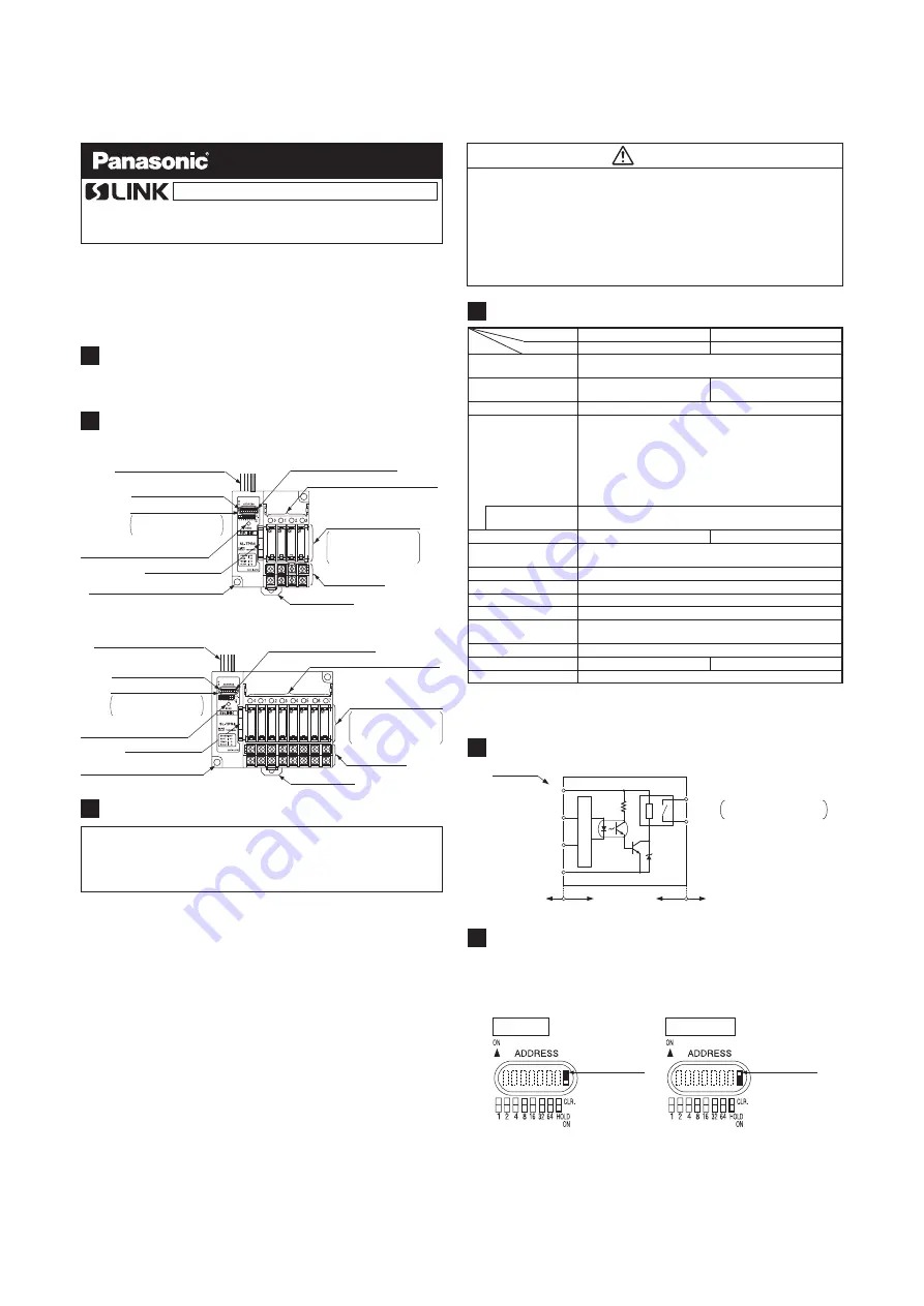
OUTPUT CIRCUIT DIAGRAM (per channel)
5
+24
V
DC (Brown)
D (White)
G (Black)
0V (Blue)
Color code
S-LINK
side
Internal circuit
Output device side
Output relay
Output
SL-TPR4
: Output 0 to 3
SL-TPR8
: Output 0 to 7
Main circuit
●
●
The output state just before occurrence of an error can be stored
at the time of a shut-down on the signal transmission line.
Hold ON (output stored) or Hold Clear (output not stored) can be
set by the output hold setting switch.
OUTPUT HOLD FUNCTION
6
Hold ON
Hold Clear
Output stored
Output hold
setting switch
Output not stored
Output hold
setting switch
INSTRUCTION MANUAL
MJE-SLTPR No.0063-18V
・
・
・
Never use this product with a device for personnel protection.
In case of using devices for personnel protection, use products
which meet laws and standards, such as OSHA, ANSI or IEC
etc., for personnel protection applicable in each region or
country.
Before touching this product, remove any electrostatic charges
that may be present on your body. There is a danger of this
product getting damaged due to the electrostatic charge.
WARNING
Note: 1) This value can change due to the switching frequency, environmental conditions, and desired
reliability level, therefore it is recommended to check this with the actual load.


