
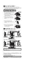
In case the first address is set outside the setting range, the outputs
which are assigned addresses exceeding 127 cannot be used.
●
Address Nos. have been assigned to the
address setting switch as shown in the right
figure.
Example: In case the first address is to be set to 85
Example: If the first address is set to 85, the output addresses are
automatically assigned in the ascending order as shown
below.
・
First address = 85
= 64 + 16 + 4 + 1
●
The sum of the address Nos. for which the address setting
switch has been set to the 'ON' side becomes the first address.
The setting range for the first address is
SL-TPR4
: 0 to 124
SL-TPR8
: 0 to 120
●
When the first address has been set, address for 4 outputs in
case of
SL-TPR4
, and for 8 outputs in case of
SL-TPR8
, are
automatically assigned in the ascending order.
ADDRESS SETTING
8
Make sure to switch off the power supply and remove electrostatic
change from your body before carrying out address setting.
Address setting switch
1 2 4 8 16 32 64
Address setting switch
1 2 4 8 16 32 64
1
+
4
+
16
+
64
=
85
ON ON ON ON
SL-TPR4
SL-TPR8
Output Output 0 Output 1 Output 2 Output 3 Output 4 Output 5 Output 6 Output 7
85
86
87
88
89
90
91
92
Address
Output Output 0 Output 1 Output 2 Output 3
85
86
87
88
Address
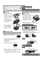
The output hold function may not operate correctly under the
following conditions:
1.
2.
3.
If the power supply connected to the control unit switches off slowly.
If it takes 5 sec., or more, for the supply voltage to fall from
24V to 10V.
If the output is directly driven by a signal from an
S-LINK
input
unit having the same address.
If a control unit which does not have the mark is used.
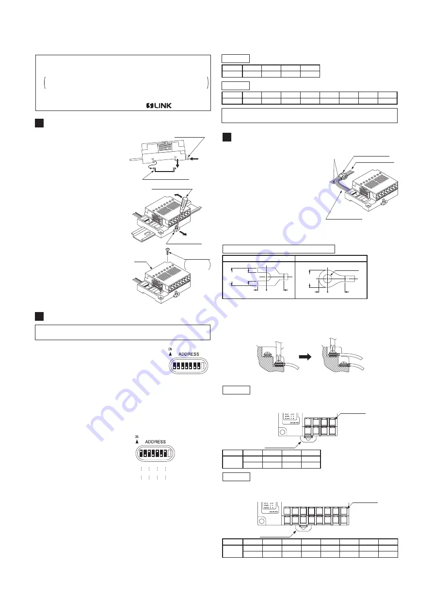
●
・
Connection to 4-core flat cable
If the exclusive flat cable has
been used for the S-LINK main /
branch cable, use the optional
exclusive hook-up connectors to
connect the 4-core flat cable of
SL-TPR4
and
SL-TPR8
to the
main / branch cable by matching
the wire colors.
●
・
Wiring on a terminal block
Use crimp terminals having dimensions given in the table below
for wiring on a terminal block.
●
Terminal arrangement diagram
・
・
・
When using the above crimp terminals, the suitable wire conduc-
tor cross-section area is 0.25 to 1.65mm
2
.
The tightening torque should be 0.3 to 0.5N
・
m.
Since the terminal block is divided into upper and lower levels,
please make connection to the lower level first.
CONNECTION
9
SL-TPR4
SL-TPR8
1
2
3
4
5
6
7
8
Output Output 0 Output 1 Output 2 Output 3 Output 4 Output 5 Output 6 Output 7
9
10
11
12
13
14
15
16
Terminal
No.
1
2
3
4
Output Output 0 Output 1 Output 2 Output 3
5
6
7
8
Terminal
No.
Match the
wire colors
ADDRESS
1 2
4 8
16 3
2 64
SEN
D
HOL
D
ON
MADE
IN JAP
AN
BR
OW
N
BLU
E
WH
ITE
BLACK
:
:
:
:
24V 0V
D
G
CLR.
S-L
INK
RE
LA
Y
TERMINA
L
ON
Exclusive hook-up
connector
4-core flat cable
Main / branch cable
Y type
Round type
5.6
or less
3 or more
4.5
or more
4
5.6
or less
4.5
or more
4
φ
3 or more
Plus screwdriver
Dimensions of suitable crimp terminals
(Unit: mm)
Upper level side
Lower level side
5 6 7 8
1 2 3 4
DIN rail stopper
Terminal No.
Output 0
Output 1
Output 2
Output 3
DIN rail stopper
Terminal No.
Upper level side
Lower level side
9 10 11 12
1 2 3 4
13 14 15 16
5 6 7 8
Output 0
Output 1
Output 2
Output 3
Output 4
Output 5
Output 6
Output 7
●
①
②
③
In case of mounting on DIN rail
Press in the DIN rail stopper
beforehand.
Fit the terminal unit rear portion
on the 35mm width DIN rail.
Press down the terminal unit
front portion on the 35mm width
DIN rail to fit it.
●
・
In case of mounting with screws
In case of mounting with
screws, use M4 pan-head
screws and the tightening
torque should be 0.8N
・
m or
less.
MOUNTING
7
①
②
③
DIN rail stopper
35mm width DIN rail
ADDRESS
1 2
4 8
16 3
2 64
SEN
D
HOL
D
ON
MADE
IN JA
PAN
BR
OW
N
BLUE
WH
ITE
BLACK
:
:
:
:
24V 0V
D
G
CLR.
S-LINK
RELA
Y
TERMINAL
ON
Flathead screw driver
DIN rail stopper
ADDRESS
1 2
4 8
16 3
2 64
SEN
D
HOL
D
ON
MAD
E IN
JAP
AN
BR
OW
N
BLU
E
WH
ITE
BLA
CK
:
:
:
:
24V 0V
D
G
CLR.
S-L
INK
RELAY
TERMINAL
ON
Cover
M4 pan-head
screw
Please arrange
separately.
*
To dismantle, insert a flathead
screwdriver in the DIN rail
stopper and pull it out till it
locks. Now, the terminal unit
can be removed.


