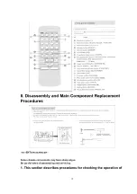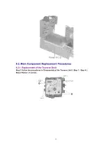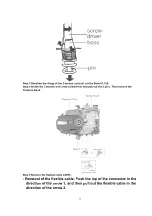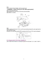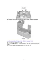
the major printed circuit boards and replacing the main
components.
2. For reassembly after operation checks or replacement, reverse
the respective procedures.
Special reassembly procedures are described only when required.
3. Select items from the following index when checks or
replacement are required.
Contents
- Disassembly Procedure for each major P.C.B.
1. Checking of the Main, Panel, Transformer, Deck P.C.B.
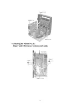
2. Checking of Power P.C.B.
- Main Component Replacement Procedures
1. Replacement of the Traverse Deck.
2. Replacement of the Power Amplifier IC.
- Disassembly and assembly of the Traverse Unit
- Disassembly and assembly of the Disc Tray
Warning:
This product uses a laser diode. Refer to caution statement “Precaution of Laser Diode.
8.1. Disassembly Procedure for each major P.C.B.
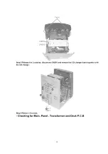
8.1.1. Checking of the Main, Panel, Transformer and Deck P.C.B.
Step 1 Remove 3 screws each side and 5 screws at rear panel.
11
Summary of Contents for SA-AK100P
Page 12: ...Step 2 Remove the Top Cabinet Step 3 Push the lever in the direction of the arrow 12...
Page 15: ...Checking for Power P C B Step 7 and 8 Remove 2 screws each side 15...
Page 49: ...20 Parts Location and Replacement Parts List Notes 49...
Page 51: ...20 1 Deck Mechanism RAA4501 1S 20 1 1 Deck Mechanism Parts Location 51...
Page 52: ...20 1 2 Deck Mechanism Parts List 52...
Page 54: ...54...
Page 55: ...20 2 2 CD Loading Mechanism Parts List 55...
Page 58: ...58...
Page 59: ...20 3 2 Cabinet Parts List 59...
Page 67: ...H601 RMR0317 8P CABLE HOLDER M 67...
Page 69: ...R116 ERJ3GEYJ102V 1K 1 16W M 69...
Page 84: ...C1041 ECEA1CKA100B 10 16V M 84...
Page 87: ...Printed in Singapore P020100001 D K J N L PRT 87...


