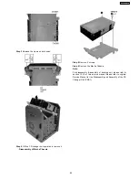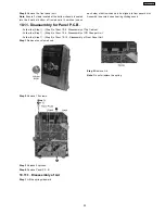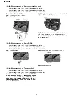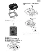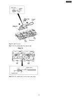
Step 1
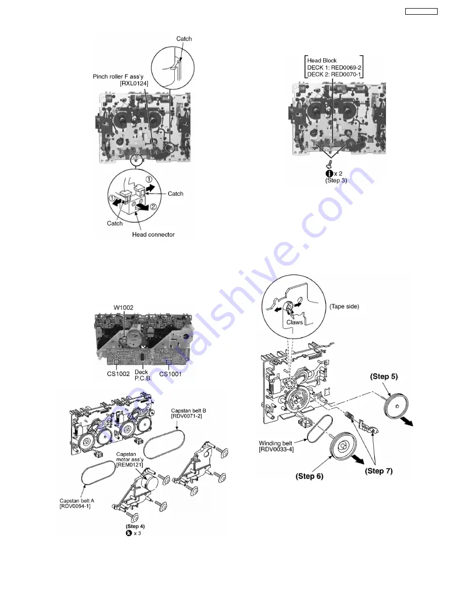
Detach the head block connector (Deck P.C.B.).
Step 2
Desolder wire(W1002) at motor assembly.
Step 3
Remove Deck P.C.B.
Step 4
Remove 3 screws (for deck 1 & 2).
Step 5
Remove capstan belt A/B.
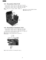
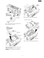
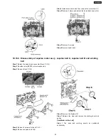
Step 1
Release the catch, and then remove the pinch roller (F).
Step 2
Release 2 claws and detach the head block connector.
Step 3
Remove 2 screws.
Step 4
Remove head block.
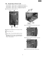
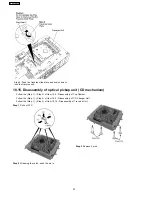
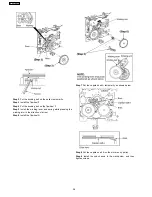
Step 6
Remove the flywheel R.
Step 7
Release the claw and remove the winding lever and
spring.
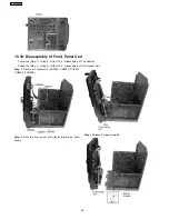
[Installation of the belt]
Step 1
The boss and marking should be positioned
horizontally.
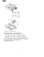
10.16.2. Disassembly of capstan motor ass’y, capstan belt A, capstan belt B and winding
belt
35
SA-AK240GCP
Summary of Contents for SA-AK240GCP
Page 13: ...8 Operating Instructions Procedures 13 SA AK240GCP ...
Page 14: ...14 SA AK240GCP ...
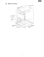
Page 23: ...10 3 Main Parts Location 23 SA AK240GCP ...
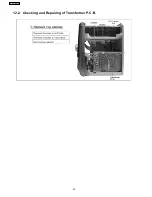
Page 40: ...12 2 Checking and Repairing of Transformer P C B 40 SA AK240GCP ...
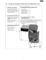
Page 41: ...12 3 Checking and Repairing of Panel Deck Deck Mechanism P C B 41 SA AK240GCP ...
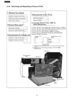
Page 42: ...12 4 Checking and Repairing of Power P C B 42 SA AK240GCP ...
Page 47: ...47 SA AK240GCP ...
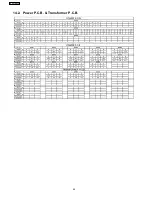
Page 48: ...14 2 Power P C B Transformer P C B 48 SA AK240GCP ...
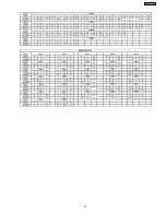
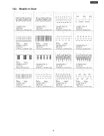
Page 49: ...14 3 Waveform Chart 49 SA AK240GCP ...
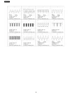
Page 50: ...50 SA AK240GCP ...
Page 52: ...52 SA AK240GCP ...
Page 58: ...58 SA AK240GCP ...
Page 60: ...SA AK240GCP 60 ...
Page 62: ...SA AK240GCP 62 ...
Page 68: ...SA AK240GCP 68 ...
Page 70: ...SA AK240GCP 70 ...
Page 74: ...SA AK240GCP 74 ...
Page 82: ...SA AK240GCP 82 ...
Page 87: ...21 Exploded Views 21 1 Cabinet Parts Location SA AK240GCP 87 ...
Page 88: ...SA AK240GCP 88 ...
Page 89: ...21 2 Deck Mechanism Parts Location RAA4502 S SA AK240GCP 89 ...
Page 90: ...21 3 Packaging SA AK240GCP 90 ...

