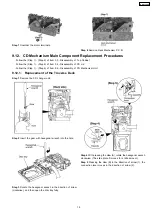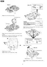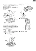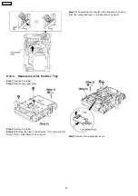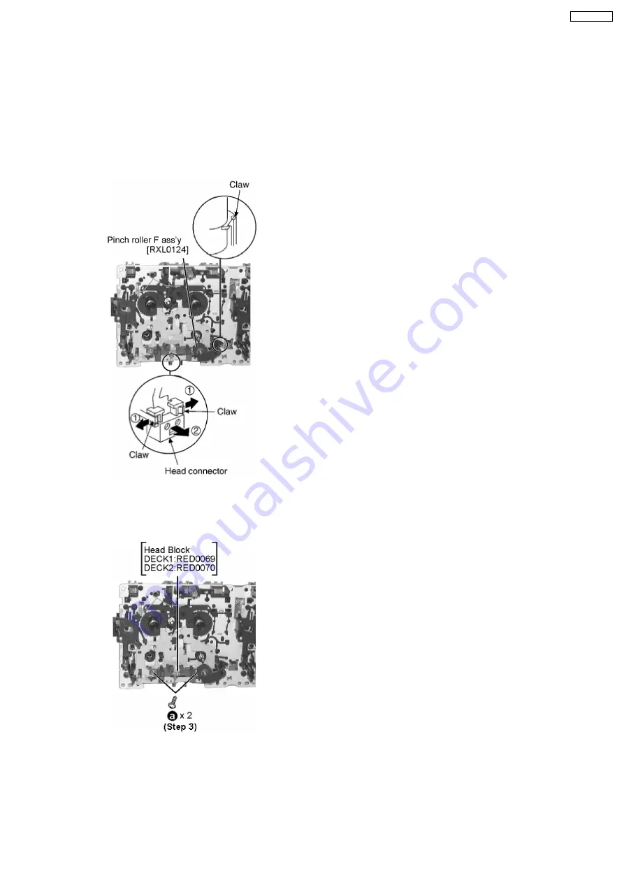
* The mechanism as shown below is for DECK1. For DECK
2, perform the same procedures.
Step 1
Release the 2 claws, and then remove the pinch roller
(R), (F).
Step 2
Release the 2 claws, and then remove the head
connector.
Step 3
Remove 2 screws.
9.13. Replacement for the pinch roller ass’y and head block
·
Follow the (Step 1) - (Step 2) of Item 9.3 - Disassembly of Top Cabinet
·
Follow the (Step 1) - (Step 6) of Item 9.4 - Disassembly of CD Lid
·
Follow the (Step 1) - (Step 3) of Item 9.6 - Disassembly of CD Mechanism Unit
·
Follow the (Step 1) - (Step 3) of Item 9.10 - Disassembly of Front Panel Unit
·
Follow the (Step 1) - (Step 5) of Item 9.11 - Disassembly of Deck Mechanism Unit
33
SA-AK330EE
Summary of Contents for SA-AK330EE
Page 8: ...7 Accessories Remote Control FM Antenna AC Cord AM Loop Antenna 8 SA AK330EE ...
Page 9: ...8 Operation Procedures 9 SA AK330EE ...
Page 10: ...10 SA AK330EE ...
Page 57: ...15 Voltage Measurement 57 SA AK330EE ...
Page 58: ...58 SA AK330EE ...
Page 89: ...21 Troubleshooting Guide 89 SA AK330EE ...
Page 91: ...22 1 Deck Mechanism RAA4502 S 22 1 1 Deck Mechanism Parts Location 91 SA AK330EE ...
Page 92: ...92 SA AK330EE ...
Page 95: ...95 SA AK330EE ...
Page 97: ...22 3 1 Cabinet Parts Location 22 3 Cabinet 97 SA AK330EE ...
Page 98: ...98 SA AK330EE ...
Page 108: ...22 6 Packaging 108 SA AK330EE PRT0412 P S J N A E ...

