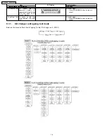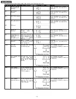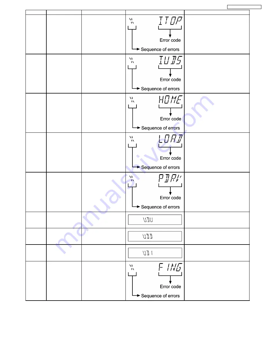
Error Code Diagnosis Contents Description of error
Automatic FL Display
Remarks
ITOP
UD assembly
UD Rack does not move to
front direction. This lead to
UD base not raise to top
position.
For CD changer unit (CRS1).
Press [SINGLE CHANGE] on main unit
for next error.
IUDS
UD assembly
After TOP SW is detected,
UD rack does not move into
tray 1 position.
For CD changer unit (CRS1).
Press [SINGLE CHANGE] on main unit
for next error.
HOME
Cam gear/gear
assembly abnormal
Cam gear does not move to
“HOME”
position
under
following conditions
1.
After tray is load to
“PLAY” position.
2.
After tray is unload to
“STOCK” position.
For CD changer unit (CRS1).
Press [SINGLE CHANGE] on main unit
for next error.
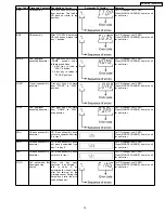
LOAD
Tray drive assembly
abnormal
Tray unit does not move
from “STOCK” to “PLAY”
position
For CD changer unit (CRS1).
Press [SINGLE CHANGE] on main unit
for next error.
PDRV
Cam gear/gear
assembly abnormal
Cam gear does not move
from “HOME” to “PLAY”
drive position.
For CD changer unit (CRS1).
Press [SINGLE CHANGE] on main unit
for next error.
UDU
UD base asssembly
abnormal
UD Base assembly does
not move upwards from tray
5 to tray 2
For CD changer unit (CRS1).
Press [SINGLE CHANGE] on main unit
for next error.
UDD
UD base asssembly
abnormal
UD Base assembly does
not move downwards from
tray 1 to tray 5.
For CD changer unit (CRS1).
Press [SINGLE CHANGE] on main unit
for next error.
UD1
UD base asssembly
abnormal
UD Base assembly does
not move to tray 1.
For CD changer unit (CRS1).
Press [SINGLE CHANGE] on main unit
for next error.
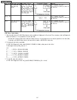
F1NG
Fail - safe mode. (For
open/close tray
unit(s))
When
the
tray
open
operation is performed, it
fails
to
open.
It
will
automatically close all trays
after the time-out by the
microprocessor. During this
time when it fails, the error
code will appear.
For CD changer unit (CRS1).
Press [SINGLE CHANGE] on main unit
for next error.
19
SA-AK340P / SA-AK340PC
Summary of Contents for SA-AK340P
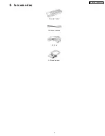
Page 9: ...6 Accessories Remote Control FM Indoor Antenna AC Cord AM Loop Antenna 9 SA AK340P SA AK340PC ...
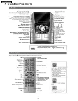
Page 10: ...7 Operation Procedures 10 SA AK340P SA AK340PC ...
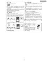
Page 11: ...11 SA AK340P SA AK340PC ...
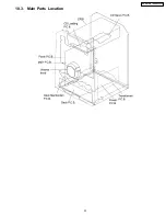
Page 23: ...10 3 Main Parts Location 23 SA AK340P SA AK340PC ...
Page 34: ...34 SA AK340P SA AK340PC ...
Page 40: ...12 2 Checking and Repairing of Transformer P C B 40 SA AK340P SA AK340PC ...
Page 41: ...12 3 Checking and Repairing of Panel Deck Deck Mechanism P C B 41 SA AK340P SA AK340PC ...
Page 42: ...12 4 Checking and Repairing of Power P C B 42 SA AK340P SA AK340PC ...
Page 47: ...14 2 Power P C B and Transformer P C B 47 SA AK340P SA AK340PC ...
Page 48: ...14 3 Waveform Chart 48 SA AK340P SA AK340PC ...
Page 56: ...56 SA AK340P SA AK340PC ...
Page 58: ...SA AK340P SA AK340PC 58 ...
Page 60: ...SA AK340P SA AK340PC 60 ...
Page 66: ...SA AK340P SA AK340PC 66 ...
Page 68: ...SA AK340P SA AK340PC 68 ...
Page 72: ...SA AK340P SA AK340PC 72 ...
Page 80: ...SA AK340P SA AK340PC 80 ...
Page 84: ...84 SA AK340P SA AK340PC ...
Page 85: ...21 Exploded Views 21 1 Cabinet Parts Location SA AK340P SA AK340PC 85 ...
Page 86: ...SA AK340P SA AK340PC 86 ...
Page 87: ...SA AK340P SA AK340PC 87 ...

