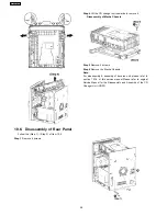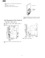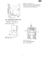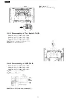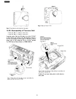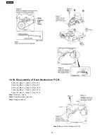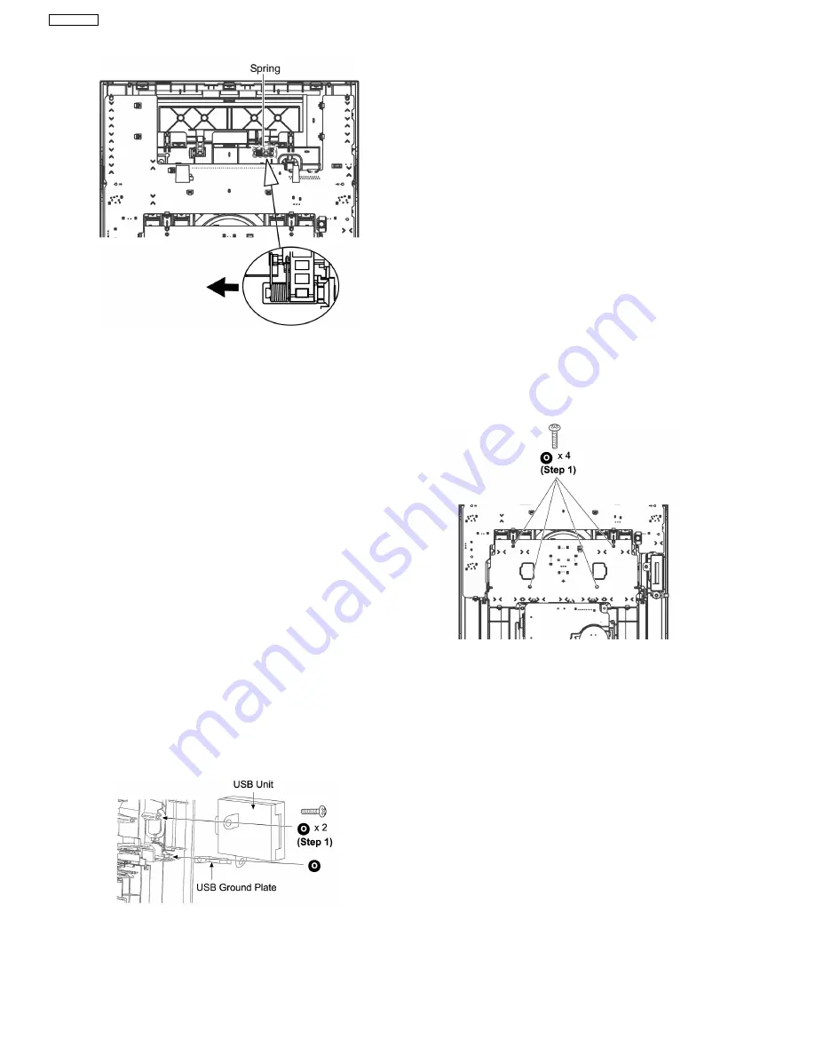
Step 1
Remove 4 screws at Tact Switch P.C.B..
Step 2
Remove Tact Switch P.C.B..
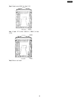
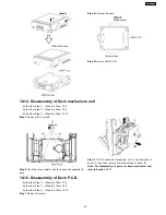
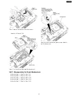
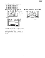
Step 1
Remove 2 screws at USB unit.
Step 2
Remove USB unit.
Step 3
Remove USB bottom case as arrow shown.
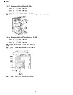
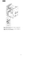
Step 2
Remove Lid.
Note:
Do not misplace the spring.
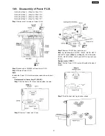
10.12. Disassembly of Tact Switch P.C.B.
·
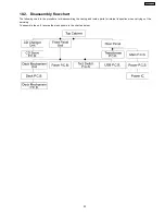
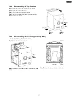
Follow the (Step 1) - (Step 5) of Item 10.4
·
Follow the (Step 1) - (Step 4) of Item 10.5
·
Follow the (Step 1) - (Step 5) of Item 10.10
10.13. Disassembly of USB P.C.B.
·
Follow the (Step 1) - (Step 5) of Item 10.4
·
Follow the (Step 1) - (Step 4) of Item 10.5
·
Follow the (Step 1) - (Step 5) of Item 10.10
34
SA-AK450PL
Summary of Contents for SA-AK450PL
Page 8: ...8 SA AK450PL ...
Page 11: ...6 Accessories Remote Control FM Antenna Wire AC Cord AM Loop Antenna 11 SA AK450PL ...
Page 12: ...7 Operating Instructions Procedures 7 1 Main Unit Key Buttons Operations 12 SA AK450PL ...
Page 13: ...7 2 Remote Control Key Buttons Operations 13 SA AK450PL ...
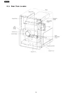
Page 26: ...10 3 Main Parts Location 26 SA AK450PL ...
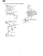
Page 38: ...10 17 1 Replacement of Pinch Roller and Head Block 38 SA AK450PL ...
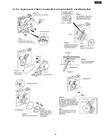
Page 39: ...10 17 2 Replacement of Motor Capstan Belt A Capstan Belt B and Winding Belt 39 SA AK450PL ...
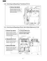
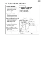
Page 45: ...12 4 Checking and Repairing of Power P C B 45 SA AK450PL ...
Page 47: ...47 SA AK450PL ...
Page 51: ...15 3 Main P C B 15 4 Panel P C B 51 SA AK450PL ...
Page 52: ...15 5 Power P C B Transformer P C B 52 SA AK450PL ...
Page 53: ...15 6 Waveform Chart 53 SA AK450PL ...
Page 62: ...SA AK450PL 62 ...
Page 64: ...64 SA AK450PL ...
Page 84: ...SA AK450PL 84 ...
Page 89: ...23 Exploded Views 23 1 Cabinet Parts Location SA AK450PL 89 ...
Page 90: ...SA AK450PL 90 ...
Page 91: ...23 2 Deck Mechanism Parts Location RAA4403 S SA AK450PL 91 ...
Page 92: ...23 3 Packaging SA AK450PL 92 ...

