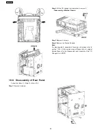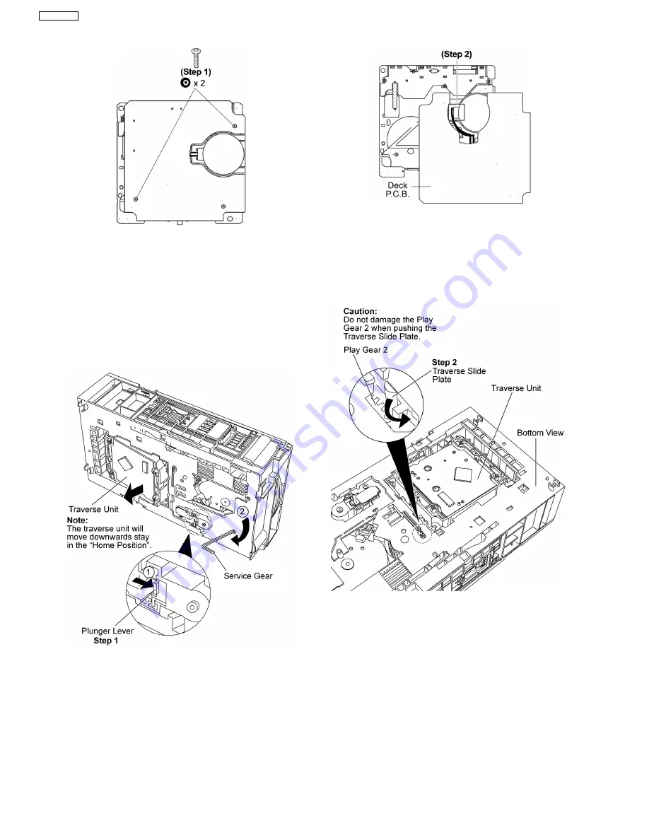
Step 2
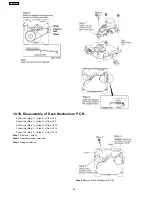
Desolder wire at deck motor terminals.
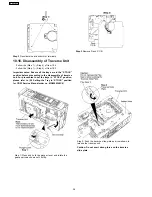
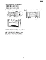
Important notes: Ensure all the trays are in the “STOCK”
position before proceeding to the disassemble of traverse
unit. For procedures to set the trays in “STOCK” position,
please refer to (5.3 Setting the Tray In “STOCK” position
for CRS1 Service Manual order no. MD0509368C0)
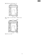
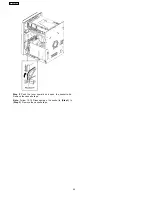
Step 1: Press and hold the plunger lever and rotate the
gear as arrows shown until it stop.
Step 3
Remove Deck P.C.B.
Step 2: Push the traverse slide plate as arrow shown to
release the traverse unit.
Caution: Do not exert strong force on the traverse
slide plate.
10.16. Disassembly of Traverse Unit
·
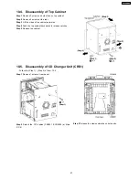
Follow the (Step 1) - (Step 5) of Item 10.4
·
Follow the (Step 1) - (Step 4) of Item 10.5
36
SA-AK450PL
Summary of Contents for SA-AK450PL
Page 8: ...8 SA AK450PL ...
Page 11: ...6 Accessories Remote Control FM Antenna Wire AC Cord AM Loop Antenna 11 SA AK450PL ...
Page 12: ...7 Operating Instructions Procedures 7 1 Main Unit Key Buttons Operations 12 SA AK450PL ...
Page 13: ...7 2 Remote Control Key Buttons Operations 13 SA AK450PL ...
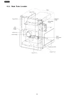
Page 26: ...10 3 Main Parts Location 26 SA AK450PL ...
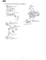
Page 38: ...10 17 1 Replacement of Pinch Roller and Head Block 38 SA AK450PL ...
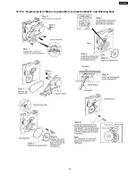
Page 39: ...10 17 2 Replacement of Motor Capstan Belt A Capstan Belt B and Winding Belt 39 SA AK450PL ...
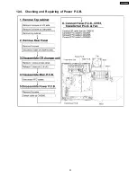
Page 45: ...12 4 Checking and Repairing of Power P C B 45 SA AK450PL ...
Page 47: ...47 SA AK450PL ...
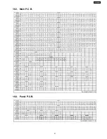
Page 51: ...15 3 Main P C B 15 4 Panel P C B 51 SA AK450PL ...
Page 52: ...15 5 Power P C B Transformer P C B 52 SA AK450PL ...
Page 53: ...15 6 Waveform Chart 53 SA AK450PL ...
Page 62: ...SA AK450PL 62 ...
Page 64: ...64 SA AK450PL ...
Page 84: ...SA AK450PL 84 ...
Page 89: ...23 Exploded Views 23 1 Cabinet Parts Location SA AK450PL 89 ...
Page 90: ...SA AK450PL 90 ...
Page 91: ...23 2 Deck Mechanism Parts Location RAA4403 S SA AK450PL 91 ...
Page 92: ...23 3 Packaging SA AK450PL 92 ...

