
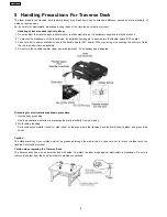
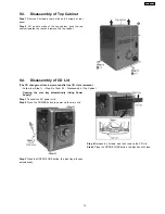
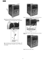
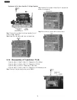
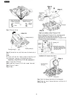
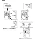
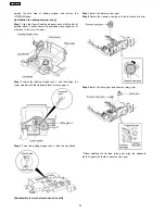
Step 1
Remove 7 screws and disconnect wire CN2810 (Fan) at
rear cabinet as shown.
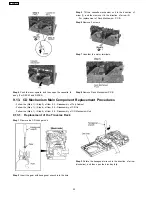
Step 1
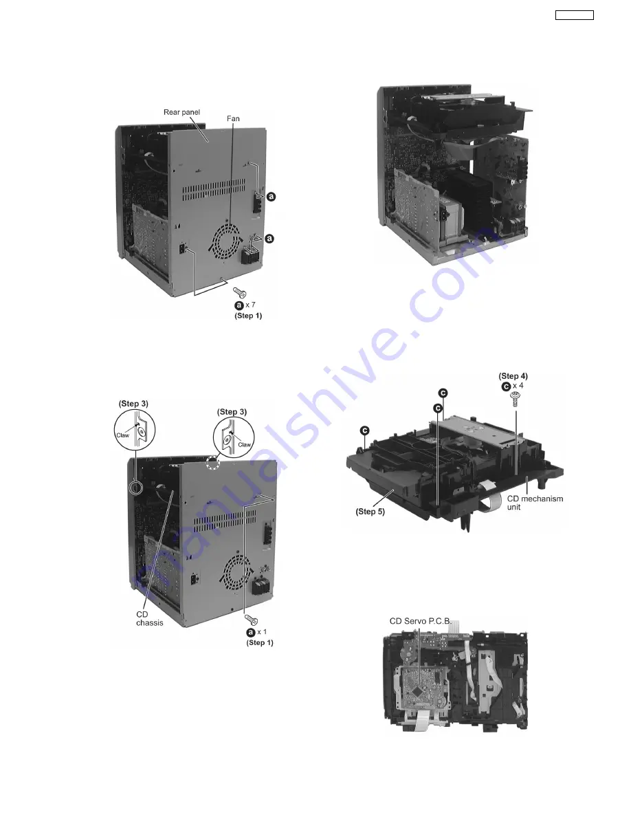
Remove one screw at rear panel.
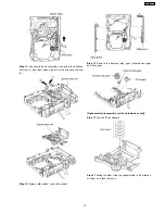
Step 2
Detach the FFC wires (CN2801 & CN2805).
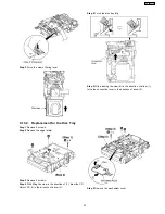
Step 3
Release the claws of both ends, and then lift up the CD
Mechanism Unit.
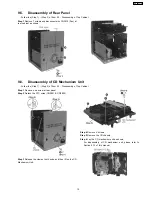
Step 4
Remove 4 screws.
Step 5
Remove the CD chassis.
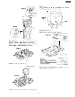
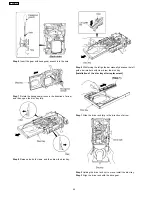
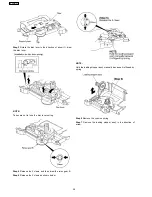
Step 6
Lay the CD mechanism unit as shown.
·
For disassembly of CD mechanism unit, please refer to
Section 9.13 of this manual.
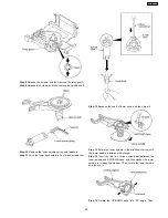
9.5. Disassembly of Rear Panel
·
Follow the (Step 1) - (Step 2) of Item 9.3 - Disassembly of Top Cabinet
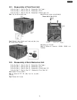
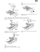
9.6. Disassembly of CD Mechanism Unit
·
Follow the (Step 1) - (Step 2) of Item 9.3 - Disassembly of Top Cabinet
15
SA-AK631PL
Summary of Contents for SA-AK631PL
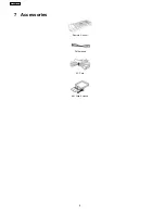
Page 8: ...7 Accessories Remote Control FM Antenna AC Cord AM Loop Antenna 8 SA AK631PL ...
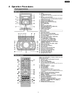
Page 9: ...8 Operation Procedures 9 SA AK631PL ...
Page 10: ...10 SA AK631PL ...
Page 59: ...15 Voltage Measurement 59 SA AK631PL ...
Page 60: ...60 SA AK631PL ...
Page 92: ...21 Troubleshooting Guide 92 SA AK631PL ...
Page 94: ...22 1 Deck Mechanism RAA3412 S 22 1 1 Deck Mechanism Parts Location 94 SA AK631PL ...
Page 95: ...95 SA AK631PL ...
Page 98: ...98 SA AK631PL ...
Page 100: ...22 3 Cabinet 22 3 1 Cabinet Parts Location 100 SA AK631PL ...
Page 101: ...101 SA AK631PL ...
Page 112: ...22 6 Packaging 112 SA AK631PL PRT0412 D S J N A E ...


